


—
4
—
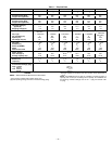
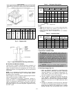
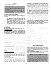
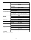
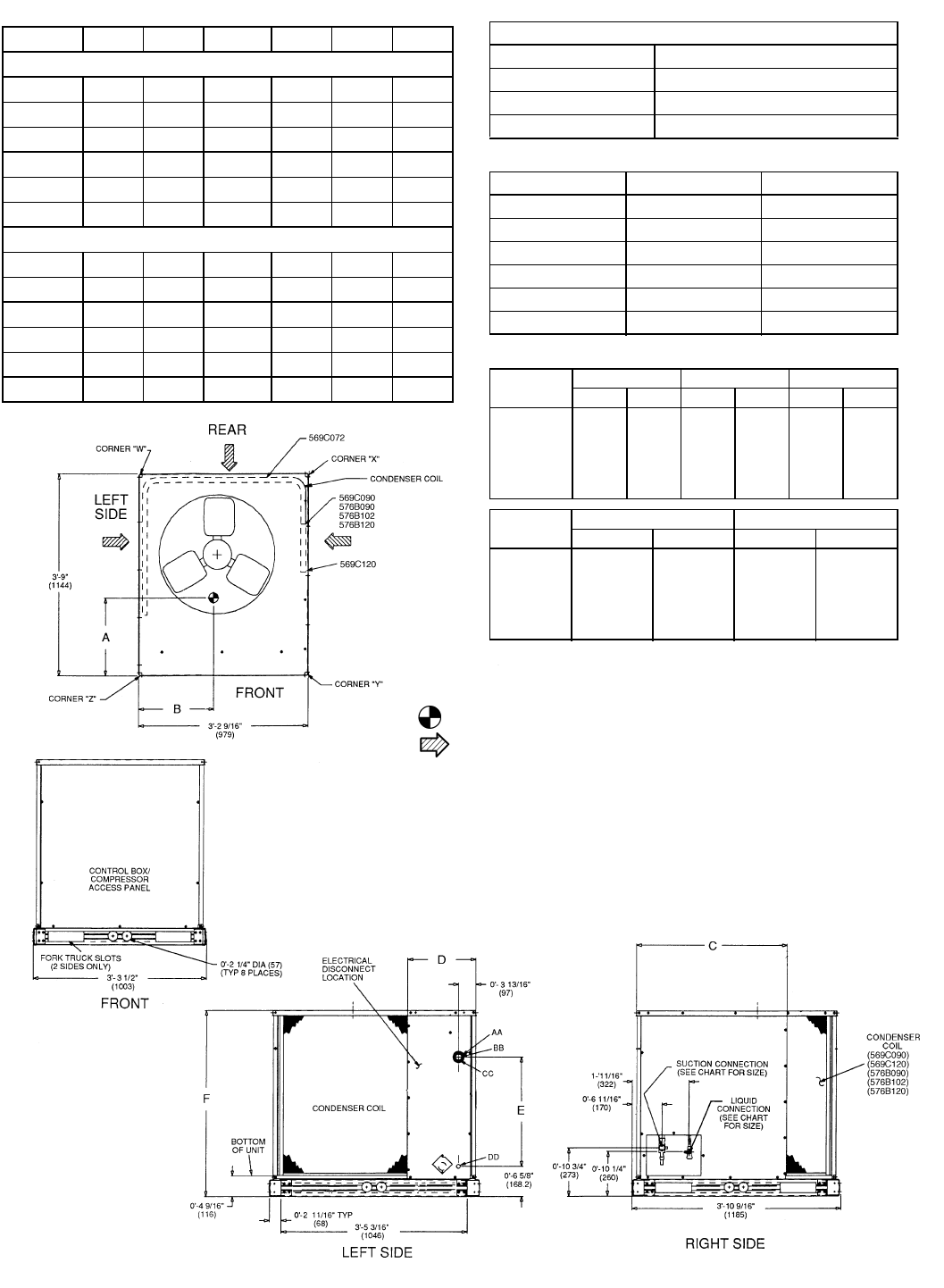
DIMENSIONS
(f
t-
i
n.
)
UNIT A B C D E F
With Aluminum Coils (Standard)
569C072
1-6
1
/
2
1-2
3
/
4
—1-2
1
/
4
1-4
5
/
16
2-9
5
/
16
569C090
1-8 1-6
1
/
2
2-9
13
/
16
1-3 2-
5
/
16
3-5
7
/
16
569C120
1-9 1-8 2-0 1-3 2-
5
/
16
3-5
7
/
16
576B090
1-6 1-4
3
/
4
2-9
13
/
16
1-3 2-
5
/
16
3-5
7
/
16
576B102
1-7 1-5 2-9
13
/
16
1-3 2-
5
/
16
3-5
7
/
16
576B120
1-7 1-5 2-9
13
/
16
1-3 2-
5
/
16
3-5
7
/
16
With Copper Coils (Optional)
569C072
1-8 1-3 — 1-2
1
/
4
1-4
5
/
16
2-9
5
/
16
569C090
1-9
1
/
2
1-6 2-9
13
/
16
1-3 2-
5
/
16
3-5
7
/
16
569C120
1-10 1-7 2-0 1-3 2-
5
/
16
3-5
7
/
16
576B090
1-7
1
/
2
1-4
1
/
2
2-9
13
/
16
1-3 2-
5
/
16
3-5
7
/
16
576B102
1-7
1
/
2
1-4 2-9
13
/
16
1-3 2-
5
/
16
3-5
7
/
16
576B120
1-7
1
/
2
1-4 2-9
13
/
16
1-3 2-
5
/
16
3-5
7
/
16
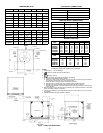
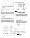
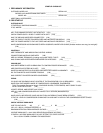
ELECTRICAL
CONNECTIONS
SERVICE VALVE CONNECTIONS
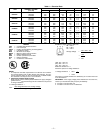
WEIGHT CHART (lb)
NOTE:
Al indicates weight with aluminum-fin coil (standard);
Cu indicates weight with copper-fin coil (optional).
CONNECTION SIZES
AA
1
3
/
8
″
Dia Field Power Supply Hole
BB
2
″
Dia Power Supply Knockout
CC
2
1
/
2
″
Dia Power Supply Knockout
DD
7
/
8
″
Dia Field Control Wiring Hole
UNIT SUCTION LIQUID
569C072
1
1
/
8
″
1
/
2
″
569C090
1
1
/
8
″
1
/
2
″
569C120
1
1
/
8
″
5
/
8
″
576B090
1
1
/
8
″
1
/
2
″
576B102
1
1
/
8
″
5
/
8
″
576B120
1
1
/
8
″
5
/
8
″
UNIT
STD UNIT CORNER W CORNER X
Al Cu Al Cu Al Cu
569C072
340 386 86 106 53 65
569C090
392 460 91 120 84 100
569C120
426 503 96 126 99 126
576B090
510 578 114 143 89 106
576B102
564 632 133 161 97 114
576B120
564 632 133 161 97 114
UNIT
CORNER Y CORNER Z
Al Cu Al Cu
569C072
77 82 124 133
569C090
105 113 113 127
569C120
117 127 113 127
576B090
133 142 173 187
576B102
141 150 193 207
576B120
141 150 193 207
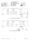
NOTES:
1. Dimensions in [ ] are in millimeters.
2. Center of Gravity. See chart for dimensions.
3. Direction of airflow.
4. Minimum clearance (local codes or jurisdiction may prevail):
a. Bottom to combustible surfaces, 0 inches.
b. Either left or rear side of condensing unit must have 36-in. clearance for proper airflow;
the remaining side(s) must have 12-in. clearance each.
c. Overhead, 60 in., to assure proper condenser fan operation.
d. Between units, control box side, 42 in. per NEC (National Electrical Code).
e. Between unit and ungrounded surfaces, control box side, 36 in. per NEC.
f. Between unit and block or concrete walls and other grounded surfaces, control box side,
42 in. per NEC.
5. With the exception of the clearance for the condenser coil as stated in Note 4b, a removable
fence or barricade requires no clearance.
6. Units may be installed on combustible floors made from wood or Class A, B, or C roof cover-
ing material.
7. Certified dimension drawings available on request.
Fig. 2 — Base Unit Dimensions