


—
5
—
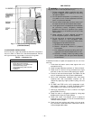
B. Filter Drier and Moisture Indicator
The filter drier is factory installed. Moisture indicator is a
field-installed accessory and should be installed just after
liquid line shutoff valve at the evaporator coil. Do not use a
receiver. A receiver is not supplied with the unit and should
not be used.
NOTE: Unit is shipped with R-22 holding charge. System
pressure must be relieved before removing caps. Recover
refrigerant prior to brazing.
Pass nitrogen or other inert gas through piping while braz-
ing to prevent formation of copper oxide.
Install field-supplied thermostatic expansion valve(s) in
evaporator section. It is recommended that a field supplied
liquid line solenoid be positioned in the main liquid line
(near the evaporator coil). It should be wired to close when
compressor stops to minimize refrigerant migration during
the ‘‘OFF’’ cycle.
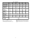
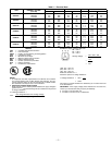
Table 2 — Refrigerant Piping Sizes
LEGEND
NOTES:
1. Pipe sizes are based on a 2° F (1° C) loss for liquid and suction
lines.
2. Pipe sizes are based on the maximum linear length shown for
each column, plus a 50% allowance for fittings.
3. Charge units with R-22 in accordance with unit installation
instructions.
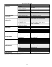
Table 3 — Liquid Line Data
NOTE:
Values shown are for units operating at 45 F (7.2 C) saturated
suction and 95 F (35 C) entering air.
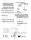
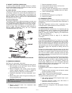
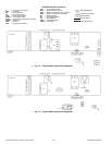
V. ELECTRICAL CONNECTIONS
A. Field Power Supply (Fig. 5-7)
1. Make all electrical connections in accordance with
NEC ANSI/NFPA (American National Standards
Institute/ National Fire Protection Association) 70,
latest edition, and local electrical codes governing
such wiring. Refer to unit wiring diagram.
2. Use only copper or copper-clad conductor fan connec-
tions between field-supplied electrical disconnect
switch and unit. DO NOT USE ALUMINUM WIRE.
Maximum wire size is no. 2 AWG (American Wire
Gage).
3. Voltage to compressor terminals during operation
must be within voltage range indicated on unit name-
plate (also see Table 4). On 3-phase units, voltages
between phases must be balanced within 2% and
LINEAR LENGTH OF PIPING — FT (M)
UNIT
0-25
(0-7.6)
25-50
(7.6-15.2)
50-75
(15.2-22.9)
75-100
(22.9-30.5)
Line Size (in. OD)
LSLSLSLS
569C072
1
/
2
1
1
/
8
1
/
2
1
1
/
8
1
/
2
1
1
/
8
1
/
2
1
1
/
8
569C090
1
/
2
1
1
/
8
1
/
2
1
1
/
8
5
/
8
1
1
/
8
5
/
8
1
3
/
8
569C120
5
/
8
1
1
/
8
5
/
8
1
3
/
8
5
/
8
1
3
/
8
5
/
8
1
3
/
8
576B090
1
/
2
1
1
/
8
1
/
2
1
1
/
8
5
/
8
1
1
/
8
5
/
8
1
3
/
8
576B102
5
/
8
1
1
/
8
5
/
8
1
1
/
8
5
/
8
1
3
/
8
5
/
8
1
3
/
8
576B120
5
/
8
1
1
/
8
5
/
8
1
1
/
8
5
/
8
1
3
/
8
5
/
8
1
3
/
8
L—
Liquid Line
S—
Suction Line
UNIT
MAX
ALLOWABLE
LIQUID LIFT
LIQUID LINE
Max Allowable
Pressure Drop
Max Allowable
Temp Loss
Ft M psi kPa F C
569C072
86 26.2 7 48.3 2 1
569C090
60 18.3 7 48.3 2 1
569C120
70 21.3 7 48.3 2 1
576B090
60 18.3 7 48.3 2 1
576B102
65 19.8 7 48.3 2 1
576B120
65 19.8 7 48.3 2 1
WARNING: The unit cabinet must have an
uninterrupted, unbroken electrical ground to minimize
the possibility of personal injury if an electrical fault
should occur. This ground may consist of electrical wire
connected to the unit ground lug in the control
compartment or conduit approved for electrical ground
when installed in accordance with the NEC and local
electrical codes. Failure to adhere to this warning could
result in personal injury.
CAUTION: Failure to follow these precautions
could result in damage to the unit being installed:
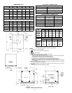
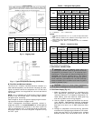
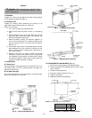
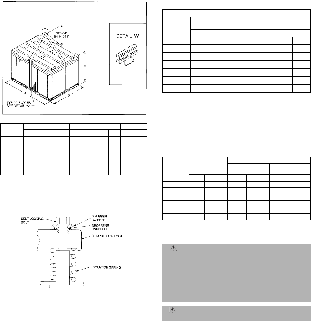
Fig. 4 — Typical Compressor Mounting (576B Units)
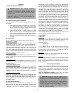
Fig. 3 — Rigging Label
*Weights are for aluminum coils.
UNIT
RIGGING WEIGHT* A B C
lb kg in. mm in. mm in. mm
569C072
390 177 45.0 1143 38.5 978 35.5 904
569C090
420 192 45.0 1143 38.5 978 43.5 1105
569C120
445 203 45.0 1143 38.5 978 43.5 1105
576B090
560 255 45.0 1143 38.5 978 43.5 1105
576B102
614 280 45.0 1143 38.5 978 43.5 1105
576B120
614 280 45.0 1143 38.5 978 43.5 1105
NOTICE TO RIGGERS
HOOK RIGGING SHACKLES THROUGH HOLES IN BASE RAIL, ON ALL FOUR SIDES.
HOLES IN BASE RAILS ARE CENTERED AROUND THE UNIT CENTER OF GRAVITY. USE
WOODEN TOP SKID, WHEN RIGGING, TO PREVENT RIGGING STRAPS FROM DAMAGING
UNIT.
CAUTION:
ALL PANELS MUST BE IN PLACE WHEN RIGGING.