


—
2
—
INSTALLATION
NOTE: When installing any accessory item, see the manufac-
turer’s installation instructions packaged with the accessory.
A qualified agency must use factory-authorized kits or acces-
sories when modifying this unit.
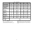
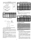
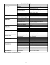
The 569C072,090, and 120 units use hermetic compressors.
The 576B090,102, and 120 units use semi-hermetic compres-
sors. Refer to Table 1.
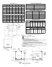
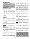
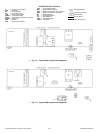
NOTE: If vibration isolators are required for a particular
installation, use corner weight information in Fig. 2 to make
proper selection.
I. LOCATE THE UNIT
A. Clearance
Maintain clearance around and above unit to provide mini-
mum distance from combustible materials, proper airflow,
and service access. Refer to Fig. 2.
Minimum clearance (local codes or jurisdiction may prevail):
a. Bottom to combustible surfaces 0 inches.
b. Condenser coil, for proper airflow, 36 in. one side, 12 in.
the other. The left or rear side receiving the greater clear-
ance is optional.
c. Overhead, 60 in. to ensure proper condenser fan
operation.
d. Between units, control box side, 42 in. per NEC (National
Electrical Code).
e. Between unit and ungrounded surfaces, control box side,
36 in. per NEC.
f. Between unit and block or concrete walls and other
grounded surfaces, control box side, 42 in. per NEC.
Although unit is weatherproof, guard against water from
higher level runoff and overhangs.
Slab-mounted units should be at least 4 in. above the highest
expected water level (flood and runoff). Do not use the unit if
it has been under water.
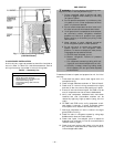
II. RIG AND PLACE UNIT
Inspect unit for transportation damage. File any claim with
transportation agency. Keep unit upright and do not drop.
Spreader bars are not required if top crating is left on unit.
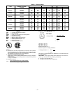
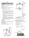
Rollers may be used to move unit across a roof. Level by
using unit frame as a reference. See Table 1 and Fig. 3
for additional information. Operating weight is shown in
Table 1.
These units are designed for overhead rigging only. Rig with
packaging assembly and wood bumper strips in place to pre-
vent unit damage by rigging cable. As further protection for
coil faces, plywood sheets may be placed against sides of
unit, behind cables. Run cables to a central suspension point
so that angle from the horizontal is not less than 45 degrees.
Raise and set unit down carefully.
If it is necessary to roll unit into position, mount unit on lon-
gitudinal rails, using a minimum of 3 rollers. Apply force to
rails, not unit. If unit is to be skidded into position, place it
on a large pad and drag it by the pad. Do not apply any force
to unit.
Raise from above to lift unit from rails or pad when unit is in
final position.
Lifting holes are provided in base rails as shown in Fig. 3.
Refer to rigging instructions on unit.
IMPORTANT: If unit has forklift protection skids, be sure to
remove forklift protection skids from under unit before set-
ting unit in place.
After unit is in position, remove shipping materials and rig-
ging skids.
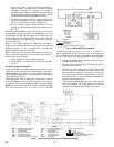
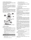
III. COMPRESSOR MOUNTING
Semi-hermetic compressors are shipped from the factory
held down by 4 bolts. After unit is installed, loosen each bolt
until the snubber washer can be moved with finger pressure
(576B units only). See Fig. 4.
IV. UNIT REFRIGERANT PIPING CONNECTIONS
Suction connections and liquid connection are sweat fittings.
Refer to Table 2 for refrigerant piping sizes. Follow standard
piping practices.
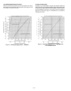
A. Size Refrigerant Lines
Consider length of piping required between condensing unit
and evaporator, amount of liquid lift, and compressor oil
return. See Table 3 for design details and line sizing. Refer
to evaporator installation instructions for additional
information.