


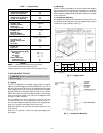
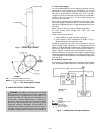
B. Oil Charging
Allow unit to run for about 20 minutes. Stop unit and check
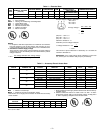
compressor oil level. Add oil only if necessary to bring oil into
view in sight glass. See Table 1 for oil charge. Use only ap-
proved compressor oil as follows:
Suniso 3GS and WF32-150
Do not reuse drained oil or use any oil that has been exposed
to atmosphere. Procedures for adding or removing oil are given
in Refrigerant Service Techniques manual.
If oil is added, run unit for additional 10 minutes. Stop unit
and check oil level. If level is still low, add oil only after de-
termining that piping system is designed for proper oil re-
turn and that system is not leaking oil.
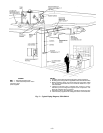
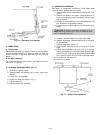
IV. REFRIGERANT SERVICE PORTS
Each unit system has 3 service ports; one on the suction line,
one on the liquid line, and one on the compressor discharge
line. Be sure caps on the ports are tight.
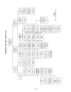
V. SEQUENCE OF OPERATION
When power is supplied to unit, the transformer (TRAN) is
energized. The crankcase heater is also energized.
A. Cooling
With the thermostat in the cooling position, and when the
space temperature comes within 2° F of the cooling set point,
the thermostat makes circuit R-O. This energizes the revers-
ing valve solenoid (RVS) and places the unit in standby con-
dition for cooling.
As the space temperature continues to rise, the second stage
of the thermostat makes, closing circuit R-Y. When compres-
sor time delay (5 ± 2 minutes) is completed, a circuit is made
to contactor (C ), starting the compressor (COMP) and outdoor-
fan motor (OFM). Circuit R-G is made at the same time, en-
ergizing the indoor-fan contactor (IFC) and starting the indoor-
fan motor (IFM) after one-second delay.
When the thermostat is satisfied, contacts open, deenergiz-
ing C. The COMP, IFM, and OFM stop.
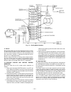
As shown in Fig. 12, cooling mode refrigerant flow is as
follows:
1. Hot refrigerant gas from compressor flows through the
reversing valve and is directed to the outdoor coil vapor
header.
2. Once at the outdoor coil vapor header, hot refrigerant
gas flows up to check valve ‘‘A,’’ which is closed. All re-
frigerant is then directed to complete a path through the
lower 6 coil circuits (6 passes in each circuit).
3. Refrigerant flows through from the liquid header side
outlets into the transfer header, where it flows upward.
4. Refrigerant leaves the transfer header through side con-
nections in 4 locations and enters the middle coil cir-
cuits (4 coil circuits above check valve ‘‘A’’).
5. Refrigerant leaves the 4 middle coil circuits and enters
the top portion of vapor header. The refrigerant moves
up to the top 2 remaining coil circuits, where it enters
the subcooler section.
6. Subcooled refrigerant leaves the coil circuits through the
side outlets. It passes through check valve ‘‘B’’ into the
system liquid line and then into the indoor coil.
7. Liquid refrigerant is expanded and evaporated to a low-
pressure vapor in the indoor coil. Refrigerant vapor then
returns to the outdoor unit through the system vapor
line, where it is drawn through the reversing valve
and accumulator and back to the compressor suction
connection.
B. Heating
On a call for heat, thermostat makes circuits R-Y and R-G.
When compressor time delay (5 ± 2 minutes) is completed, a
circuit is made to C, starting COMP and OFM. Circuit R-G
also energizes IFC and starts IFM after a 1-second delay.
If room temperature continues to fall, circuit R-W is made
through second-stage thermostat bulb. If optional electric heat
package is used, a relay is energized, bringing on supplemen-
tal electric heat. When thermostat is satisfied, contacts
open, deenergizing contactor and relay; motors and heaters
deenergize.
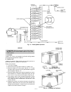
As shown in Fig. 13, heating mode refrigerant flow is as
follows:
1. Hot gas from compressor flows through the reversing valve
and is directed to the system vapor line and indoor coil
vapor header (not shown). Refrigerant is condensed and
subcooled in the indoor coil and returns to the outdoor
unit through the system liquid line.
2. Check valve ‘‘B’’ is closed and all liquid refrigerant en-
ters the liquid header.
3. Refrigerant leaves the liquid header through 12 loca-
tions. It is then expanded in fixed orifice metering de-
vices contained within the outlet tubes.
4. Refrigerant evaporates to low pressure vapor as it com-
pletes its passage through the 12 parallel coil circuits
(6 passes each).
5. Refrigerant moves from the coil circuits into the vapor
header, where it is drawn through the reversing valve
and accumulator and back to compressor suction
connection.
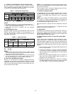
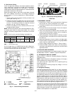
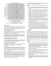
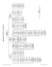
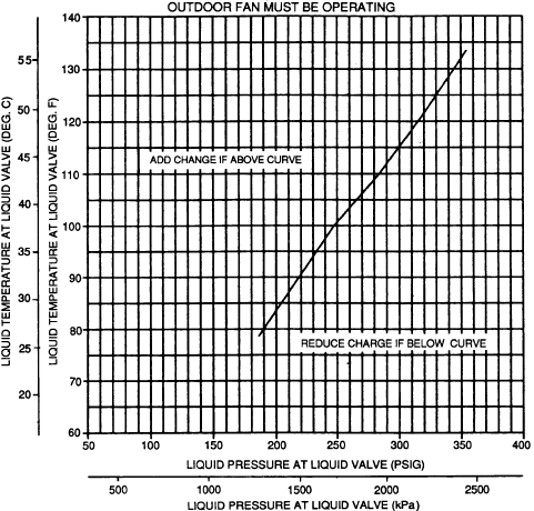
Fig. 11 — Cooling Charging Chart — 575A090
—9—