


IV. MAKE ELECTRICAL CONNECTIONS
WARNING:
Unit cabinet must have an uninterrupted,
unbroken electrical ground to minimize the possibility
of personal injury if an electrical fault should occur. This
ground may consist of electrical wire connected to unit
ground lug in control compartment, or conduit ap-
proved for electrical ground when installed in accor-
dance with National Electrical Code (NEC) ANSI
(American National Standards Institute)/NFPA 70
(National Fire Protection Association) and local electri-
cal codes. Failure to follow this warning could result in
the installer being liable for personal injury of others.
A. Field Power Supply
All units except 208/230-v units are factory wired for the volt-
age shown on the nameplate. If the 208/230-v unit is to be
connected to a 208-v power supply, the transformer must be
rewired by disconnecting the black wire from the 230-v
orange wire on the transformer and connecting it to the 208-v
red wire from the transformer. The end of the orange wire
must then be insulated.
Refer to unit label diagram for additional information. Short
wire leads (pigtails) are provided for field wire connections.
Use factory-supplied splices or UL approved copper/aluminum
connector.
When installing units, provide a disconnect per NEC.
All field wiring must comply with NEC and local
requirements.
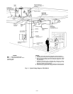
Install field wiring as follows:
1. Install conduit through side panel openings.
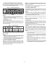
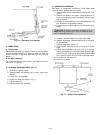
2. Install power lines to connections as shown in Fig. 8.
Wrap connections with electrical tape.
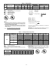
Voltage to compressor terminals during operation must be
within voltage range indicated on unit nameplate (also see
Table 4). Voltages between phases must be balanced within
2% and the current within 10%. Use the formula shown in
Table 4, Note 2, to determine the percentage of voltage im-
balance. Operation on improper line voltage or excessive phase
imbalance constitutes abuse and may cause damage to elec-
trical components. Such operation invalidates any applicable
unit warranty.
B. Accessory Electric Heat
If the system is to be equipped with an accessory electric heater,
refer to the 524A-H090 installation instructions and Table 5.
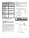
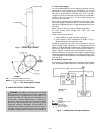
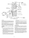
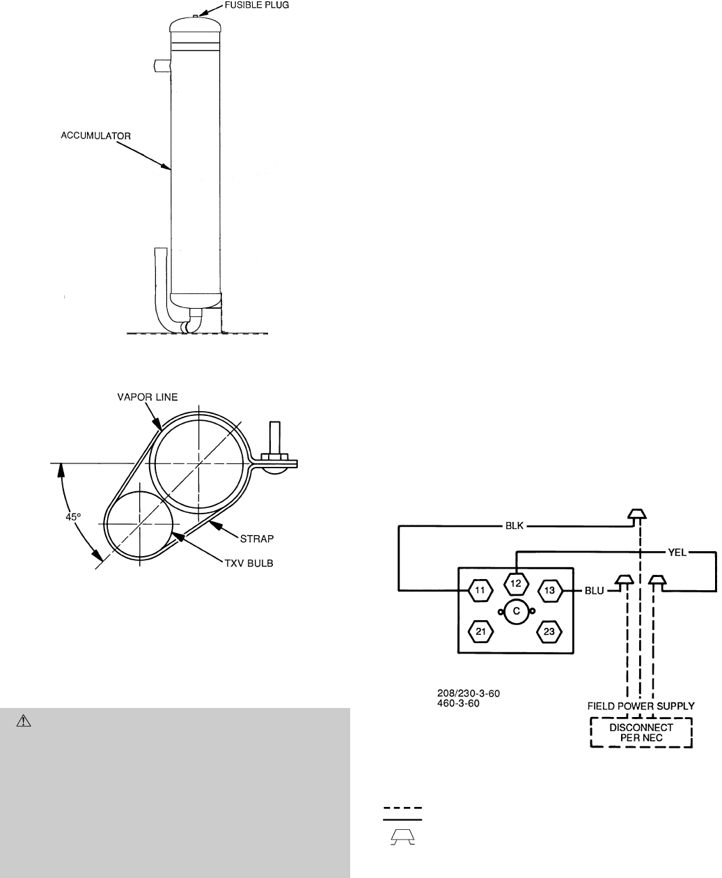
Fig. 6 — Fusible Plug Locations
LEGEND
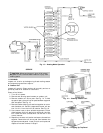
TXV — Thermostatic Expansion Valve
NOTE: The 8 o’clock position is shown above.
Fig. 7 — TXV Sensing Bulb Location
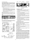
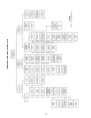
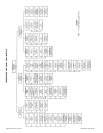
LEGEND
C—Contactor
NEC — National Electrical Code
Field Wiring
Factory Wiring
Splice Connection
(Factory Supplied)
Fig. 8 — 575A090 Power Wiring Connections
—6—