


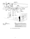
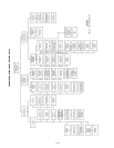
III. COMPLETE REFRIGERANT PIPING CONNECTIONS
Suction connection is sweat with plastic cap; liquid connec-
tion is sweat with plastic cap. Refer to Table 2 for the proper
line sizes. Follow standard piping practices.
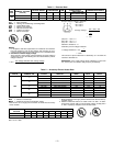
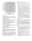
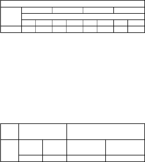
Table 2 — Refrigerant Piping Sizes
LINEAR LENGTH OF PIPING — ft
UNIT
575A
0-25 25-50 50-75 75-100
Line Size (in. OD)
LSLSLSLS
090
1
⁄
2
1
1
⁄
8
5
⁄
8
1
1
⁄
8
5
⁄
8
1
3
⁄
8
3
⁄
4
1
3
⁄
8
LEGEND
L—Liquid Line OD — Outside Diameter S—Suction Line
NOTES:
1. Pipe sizes are based on a 2° F loss for liquid and suction lines.
2. Pipe sizes are based on the maximum linear length shown for each
column, plus a 50% allowance for fittings.
3. Charge units with R-22 in accordance with unit installation
instructions.
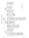
A. Size Refrigerant Lines
Consider length of piping required between 575A unit and
524A-H unit, amount of liquid lift, and compressor oil re-
turn. See Table 3. Refer to 524A installation instructions for
additional information.
Table 3 — Liquid Line Data
UNIT
575A
MAX
ALLOWABLE
LIQUID LIFT (ft)
LIQUID LINE
090
Heating Cooling
Max Allowable
Pressure Drop
(psi)
Max Allowable
Temp Loss
(F)
75 65 7 2
LEGEND
db — Dry Bulb
wb — Wet Bulb
NOTES:
1. The liquid lift in cooling mode is based on 80/67 F (db/wb ) entering
indoor-air temperature and a 95 F outdoor-air temperature, with R-22
refrigerant, at an indoor airflow of 3000 cfm.
2. The liquid lift in heating mode is based on 70/60 F (db/wb) entering
indoor-air temperature and a 47/43 F (db/wb) outdoor-air tempera-
ture, with R-22 refrigerant, at an indoor airflow of 3000 cfm.
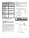
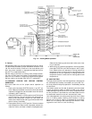
B. Filter Drier and Moisture Indicator
See Fig. 5. The filter drier is factory supplied and field-
installed in the liquid line. Moisture indicator is field-
supplied and should be installed just after liquid line shutoff
valve. Do not use a receiver; there is none provided with unit
and one should not be used.
NOTE: Unit is shipped with R-22 holding charge. System pres-
sure must be relieved before removing caps. Recover refrig-
erant prior to brazing.
Pass nitrogen or other inert gas through piping while braz-
ing to prevent formation of copper oxide.
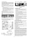
C. Liquid Line Solenoid Valve
A field-supplied liquid line solenoid valve (LLSV) is recom-
mended when piping system length exceeds 75 feet. The LLSV
must be of the biflow type, suited for use in heat pump
systems.
NOTE: Part number EF23JS214 (Sporlan model CB14S2,
5
⁄
8
-in. ODF/
7
⁄
8
-in. ODM) is recommended and is available from
the Replacement Components Division. This solenoid re-
quires field-supplied Sporlan MKC-2 coils.
Wire the solenoid in parallel with the compressor contactor
coil.
Install the LLSV near the outdoor unit. The flow arrow must
be pointed toward the outdoor unit.
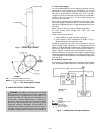
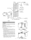
D. Safety Relief
A fusible plug is located on top of the accumulator. See Fig. 6.
Note that all safety relief components are factory installed.
Do not cap fusible plug. If local code requires additional
safety device(s), install as directed.
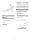
E. Suction Piping at Indoor Coil and TXV Sensing Bulb
Location
Suction piping must be designed so that refrigerant is thor-
oughly mixed after it leaves the indoor coil suction header.
The thermostatic expansion valve (TXV) sensing bulb must
also be correctly located. This ensures that the TXV sensing
bulb receives reliable readings. Install the suction piping as
follows:
1. Install a minimum of two 90-degree elbows upstream of
the TXV bulb location.
2. Locate the TXV bulb on a vertical riser where possible.
If a horizontal location is necessary, secure the bulb at
approximately the 4 o’clock position or the 8 o’clock po-
sition. See Fig. 7.
3. Make sure that the piping system has no inherent oil
traps, and that the piping layout does not allow oil to
migrate into an idle indoor coil.
4. Complete refrigerant piping from indoor coil to outdoor
coil before opening liquid and suction lines at the 575A
unit. See Tables 1 and 2 for piping selection data.
—4—