


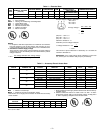
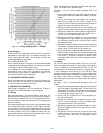
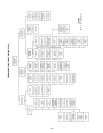
UNIT
575A
UNIT W/
ALUMINUM-FIN
COIL
UNIT W/
COPPER-FIN
COIL
WEIGHT (WITH ALUMINUM-FIN COIL) WEIGHT (WITH COPPER-FIN COIL)
Std Unit Corner W Corner X Corner Y Corner Z Std Unit Corner W Corner X Corner Y Corner Z
Dim. A Dim. B Dim. A Dim. B Lb Kg Lb Kg Lb Kg Lb Kg Lb Kg Lb Kg Lb Kg Lb Kg Lb Kg Lb Kg
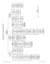
090
1Ј-8Љ
[508.0]
1Ј-5Љ
[431.8]
1Ј-9
1
⁄
2
Љ
[546.0]
1Ј-4
3
⁄
4
Љ
[425]
540 245 132 60 100 45 133 60 175 80 608 276 160 73 117 53 142 64 189 86
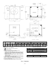
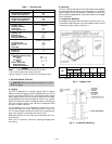
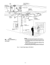
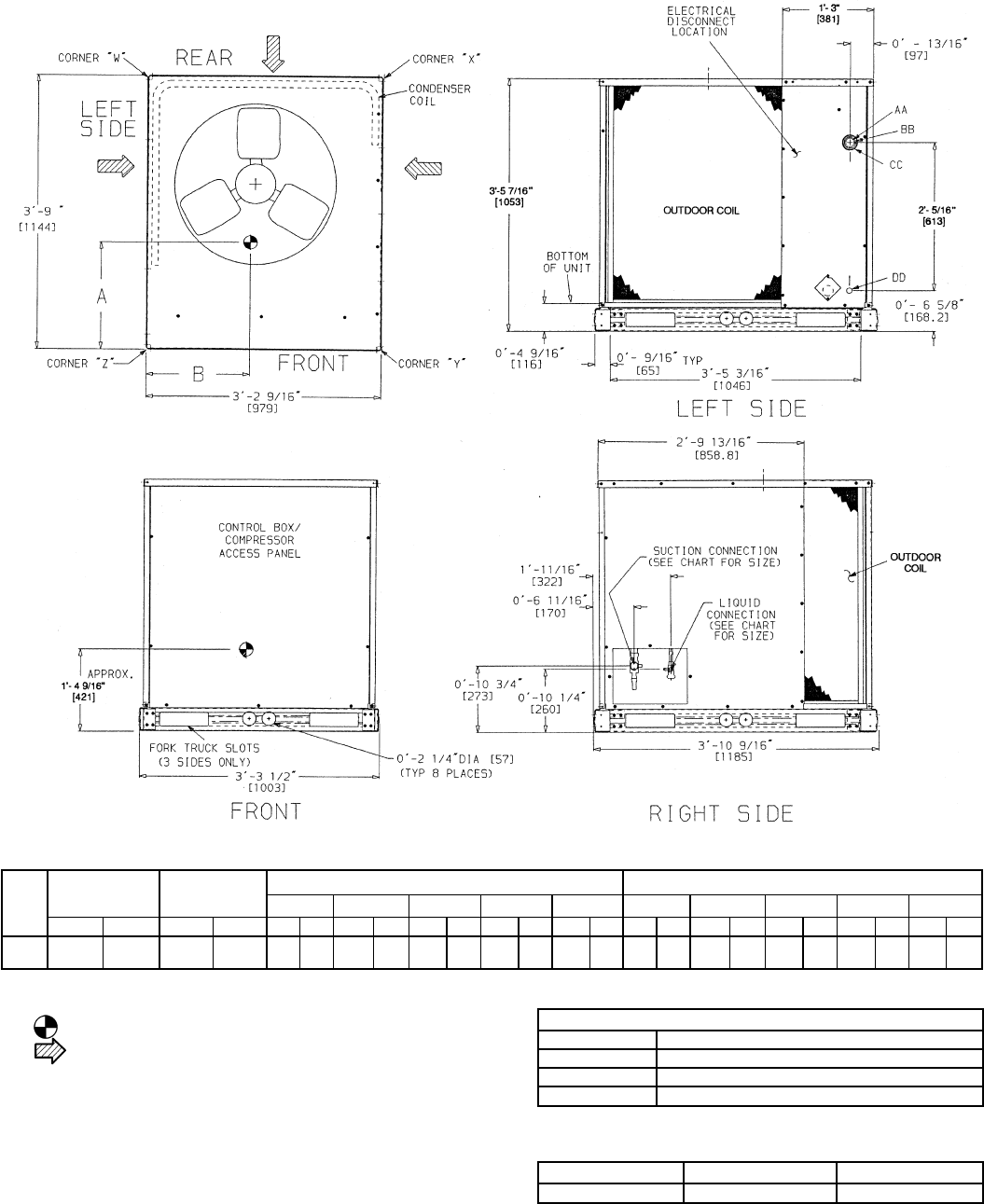
NOTES:
1. Dimensions in [ ] are in millimeters.
2. Center of Gravity. See chart for dimensions.
3. Direction of airflow.
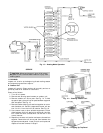
4. Minimum clearance (local codes or jurisdiction may prevail):
a. Bottom to combustible surfaces, 0 in. (0 mm)
b. Outdoor coil, for proper airflow, 36 in. (914 mm) one side, 12 in.
(305 mm) the other. The side getting the greater clearance is optional.
c. Overhead, 60 in. (1524 mm) to assure proper outdoor-fan operation.
d. Between units, control box side, 42 in. (1067 mm) per National
Electrical Code (NEC).
e. Between unit and ungrounded surfaces, control box side, 36 in.
(914 mm) per NEC.
f. Between unit and block or concrete walls and other grounded surfaces,
control box side, 42 in. (1067 mm) per NEC.
5. With the exception of the clearance for the outdoor coil as stated in
note 4b, a removable fence or barricade requires no clearance.
6. Units may be installed on combustible floors made from wood or Class A,
B, or C roof covering material.
7. Vertical center of gravity is approximately 40% of total unit height.
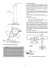
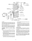
ELECTRICAL CONNECTIONS
CONNECTION SIZES
AA 1
3
⁄
8
Љ Dia. [35] Field Power Supply Hole
BB 2Љ Dia. [51] Power Supply Knockout
CC 2
1
⁄
2
Љ Dia. [64] Power Supply Knockout
DD
7
⁄
8
Љ Dia. [22] Field Control Wiring Hole
SERVICE VALVE CONNECTIONS
UNIT SUCTION LIQUID
575A090 1
1
⁄
8
Љ [28.6]
1
⁄
2
Љ [12.7]
Fig. 2 — Dimensions
—2—