


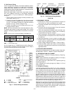
C. Defrost
Defrost board (DB) is a time and temperature control, which
includes a field-selectable time period between checks for frost
(30, 50, and 90 minutes). Electronic timer and defrost cycle
start only when contactor is energized and defrost thermo-
stat (DFT) is closed (below 28 F).
Defrost mode is identical to Cooling mode, except outdoor-
fan motor (OFM) stops and a bank of supplemental electric
heat turns on to warm air supplying the conditioned space.
Defrost mode is terminated when the DFT reaches 65 F.
VI. CHECKING COOLING AND HEATING CONTROL
OPERATION
Start and check the unit for proper control operation as
follows:
1. Place room thermostat SYSTEM switch in an OFF po-
sition. Observe that blower motor starts when FAN switch
is placed in ON position and shuts down when FAN switch
is placed in AUTO position.
2. Place SYSTEM switch in COOL position and FAN switch
in AUTO position. Set control below room temperature.
Observe that compressor, outdoor fan, and indoor fan
motors start. Observe that cooling cycle shuts down when
control setting is satisfied.
3. Place system switch in HEAT position. Set control above
room temperature. Observe that compressor, outdoor fan,
indoor-fan motor, and electric heaters (if equipped) start.
Observe that heating cycle shuts down when control set-
ting is satisfied.
4. When using an automatic changeover room thermostat,
place both SYSTEM and FAN switches in AUTO posi-
tions. Observe that unit operates in Cooling mode when
temperature control is set to call for cooling (below room
temperature), and unit operates in Heating mode when
temperature control is set to call for heating (above room
temperature).
VII. MALFUNCTION
The high-pressure switch, loss-of-charge switch, and compres-
sor overtemperature safety are located in a Cycle-LOC™ cir-
cuit that prevents heat pump operation if these safety devices
are activated.
The lockout system can be reset by adjusting the thermostat
to open the contacts (down for heating mode, up for cooling
mode) deenergizing the Cycle-LOC circuitry. Compressor over-
current protection is achieved with overload breakers which
are temperature-sensitive and will automatically reset.
Unit is equipped with a no-dump reversing valve circuit. When
unit is in cooling mode, reversing valve remains in cooling
position until a call for heating is requested by thermostat.
When unit is in heating mode, reversing valve remains in heat-
ing position until there is a call for cooling.
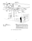
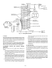
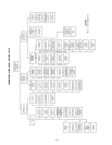
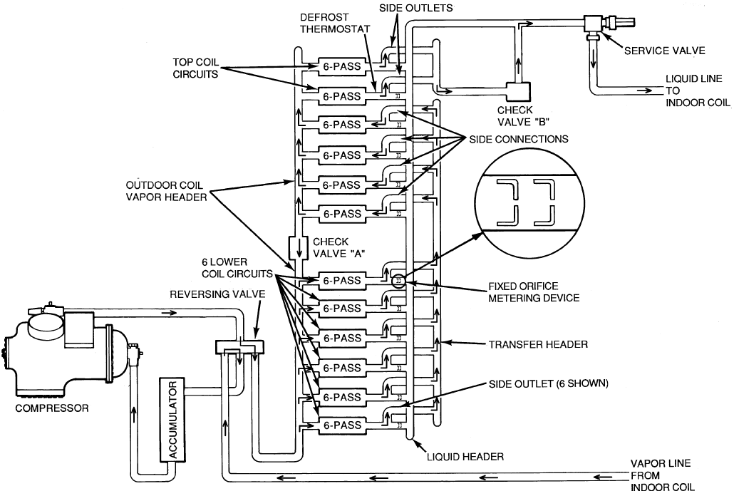
Fig. 12 — Cooling Mode Operation
—10—