


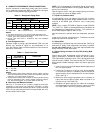
C. Field Control Wiring
Install an approved accessory thermostat assembly accord-
ing to installation instructions included with the accessory.
Locate thermostat assembly on a solid wall in the condi-
tioned space to sense average temperature in accordance with
thermostat installation instructions.
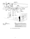
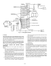
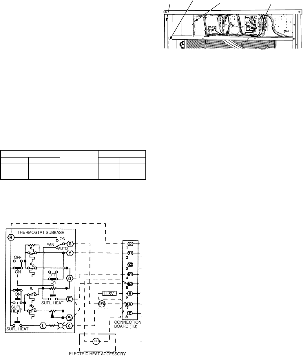
Route thermostat cable or equivalent single leads of colored
wire from subbase terminals to low-voltage connections
on unit (shown in Fig. 9) as described in following Steps 1
through 3:
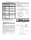
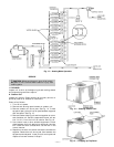
1. Pass the control wires through the hole provided in the
corner post. (See Fig. 10.)
2. Feed wire through the raceway built into the corner post
to the 24-v barriers located on the left side of the con-
trol box. The raceway provides the required clearance
between the high- and low-voltage wiring.
3. Connect thermostat wires to screw terminals of low-
voltage connection board.
NOTE: 39 VA is available for field-installed accessories. Con-
trol power requirement for heat pump outdoor unit is 36 VA
(sealed). The factory-supplied control transformer is rated at
75 VA.
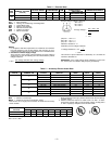
NOTE: For wire runs, use the following insulated wire:
LENGTH
INSULATION
RATING (C)
SIZE
Ft M AWG sq mm
0-50 0-15.2 35 18 0.82
50-75 15.2-22.9 35 16 1.30
Over 75 Over 22.9 35 14 2.08
LEGEND
AWG — American Wire Gage
All wire larger than no. 18 AWG (American Wire Gage) can-
not be directly connected to the thermostat and will require
a junction box and splice at the thermostat.
START-UP
I. PRELIMINARY CHECKS
1. Check that all internal wiring connections are tight and
that all barriers, covers, and panels are in place.
2. Field electrical power source must agree with unit name-
plate rating.
3. Ensure all service valves are open. Ensure all compres-
sor service valves are backseated.
4. Verify that compressor holddown bolts have been loos-
ened and that flat/snubber washers can be rotated by
finger pressure (snug, but not tight).
5. Verify compressor crankcase heater is securely in place.
Crankcase heater must operate for at least 24 hours be-
fore start-up.
6. Note that compressor oil level is visible in the sight glass.
7. Check for leaks in refrigerant system by using soap bubbles
and/or electronic leak detector.
8. Check voltage imbalance as shown in Table 4, Note 2.
9. Check that both outdoor and indoor units are properly
mounted in accordance with installation instructions and
applicable codes.
II. EVACUATE AND DEHYDRATE
Evacuate and dehydrate entire refrigerant system using meth-
ods described in GTAC II, Module 4, System Dehydration.
III. REFRIGERANT AND OIL CHARGE
Refer to GTAC II, Module 5, Charging Recovery, Recycling,
and Reclamation.
NOTE: Use of a Totalclaim refrigeration recovery unit is highly
recommended when recovering refrigerant.
Unit panels must be in place when unit is operating during
charging procedure.
Unit is shipped with holding charge only. Weigh in 15 lb of
R-22 to start unit.
A. Refrigerant Charging
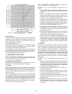
Use Cooling Charging Chart (see Fig. 11). Vary refrigerant
until the conditions of the chart are met. Note that charging
chart is different from the type normally used. Chart is based
on charging the units to the correct subcooling for the vari-
ous operating conditions. Accurate pressure gage and tem-
perature sensing device are required. Connect the pressure
gage to the service port on the liquid line service valve. Mount
the temperature sensing device on the liquid line, close to the
liquid line service valve, and insulate it so that outdoor am-
bient temperature does not affect the reading. Indoor airflow
must be within the normal operating range of the unit.
Operate unit a minimum of 15 minutes. Ensure pressure and
temperature readings have stabilized. Plot liquid pressure and
temperature on chart and add or reduce charge to meet curve.
Adjust charge to conform with charging chart, using liquid
pressure and temperature to read chart.
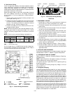
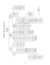
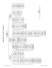
LEGEND
C—Cooling
H—Heating
HR — Heater Relay
IFC — Indoor Fan Contactor
LLSV — Liquid Line Solenoid
Valve
SUPL — Supplemental
TB — Terminal Block
Fig. 9 — Control Wiring Connections
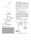
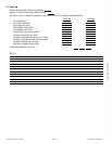
CORNER
POST
RACEWAY THERMOSTAT
FIELD CONNECTION
POWER WIRING
CONNECTIONS
Fig. 10 — Field Control Wiring Raceway
—8—