


16
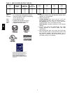
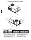
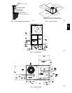
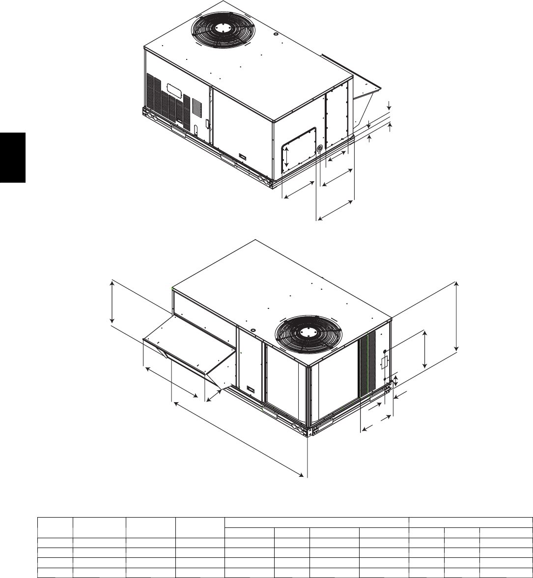
CURBS & WEI GHTS DIMENSIONS -- CHASSIS 1
Corner
D
Corner
A
Corner
B
Corner
C
6 1/8”
7”
10 1/2”
19 1/2”
22”
16 1/4”
11 3/8”
C08001
21 1/4”
19 1/2”
33 3/8”
16”
74 3/8”
J
4 5/8”
K
6 5/8”
C08000
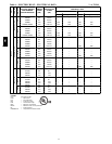
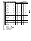
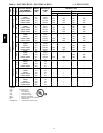
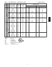
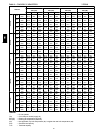
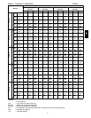
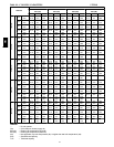
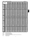
Table 7 – BASE UNIT DIMENSIONS -- CHASSIS 1
UNIT
OPERATING
WGT (LB)
SHIPPING
WGT (LB)
J
CORNER WEIGHTS (LB) CENTER OF GRAVITY (IN)
A B C D X Y HEIGHT
04 438 475 33 5/16” 108 115 110 104 38 23 17 1/4
05 494 530 33 5/16” 122 130 125 117 38 23 17 1/2
06 524 560 33 5/16” 130 138 132 124 38 23 17 3/4
07 607 645 41 5/16” 150 160 153 144 38 23 20 3/4
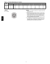
NOTES:
1. If one side has at least 36” (914mm) of clearance, the
opposite side ca n be reduced to 12” (305mm). Make
sure to plan for OA handler, if equipped.
2. Clearance o f 0” requires use of an alternate drain con-
nection.
3. Maintain 36” (914mm) between co ntrol box and groun-
ded surface or 42” (1067mm) between control box and
ungrounded surfaces (concret e or block wall).
4. Keep combustible material at 36” (914mm) away from
the flue discharge. Accessory flue discharge deflector
may allow smaller clearance.
5. Units shown with optional economizer.
6. Local codes and jurisdictions may prevail.
7. Height is measured from bottom of base rail.
558J