


IV. FIELD CONNECTIONS
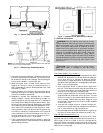
A. External Trap Condensate Drain
The unit’s
3
⁄
4
-in. condensate drain connections are located
on the bottom and side of the unit. Unit discharge connec-
tions do not determine the use of drain connections; either
drain connection can be used with vertical or horizontal
applications.
When using the standard side drain connection, make sure
the plug in the alternate bottom connection is tight before in-
stalling the unit.
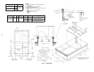
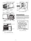
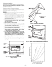
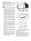
To use the bottom drain connection for a roof curb installa-
tion, relocate the factory-installed plug from the bottom con-
nection to the side connection. See Fig. 7. The piping for the
condensate drain and external trap can be completed after
the unit is in place.
All units must have an external trap for condensate drain-
age. Install a trap at least 4-in. deep and protect against freeze-
up. See Fig. 8. If drain line is installed downstream from the
external trap, pitch the line away from the unit at 1 in. per
10 ft of run. Do not use a pipe size smaller than the unit
connection.
B. Field Duct Connections
NOTE: The design and installation of the duct system must
be in accordance with NFPA standards for the installation of
nonresidence-type air conditioning and ventilating systems,
NFPA No. 90A or residence-type, NFPA No. 90B, and/or local
codes and ordinances.
Adhere to the following criteria when selecting, sizing and
installing the duct system:
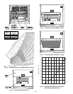
1. Remove appropriate panels from unit to obtain either
horizontal or vertical discharge. If units are installed in
horizontal discharge applications, remove vertical dis-
charge duct covers, save screws and install covers over
vertical duct openings.
2. Select and size ductwork, supply-air registers and return-
air grilles according to ASHRAE (American Society of
Heating, Refrigeration and Air-Conditioning Engi-
neers) recommendations.
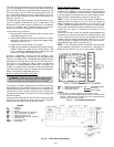
CAUTION:
When drilling the duct system fastening
holes into the side of the unit for duct flanges, be care-
ful not to puncture the coil or coil tubes. See Fig. 9.
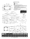
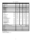
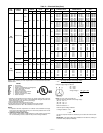
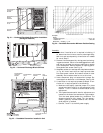
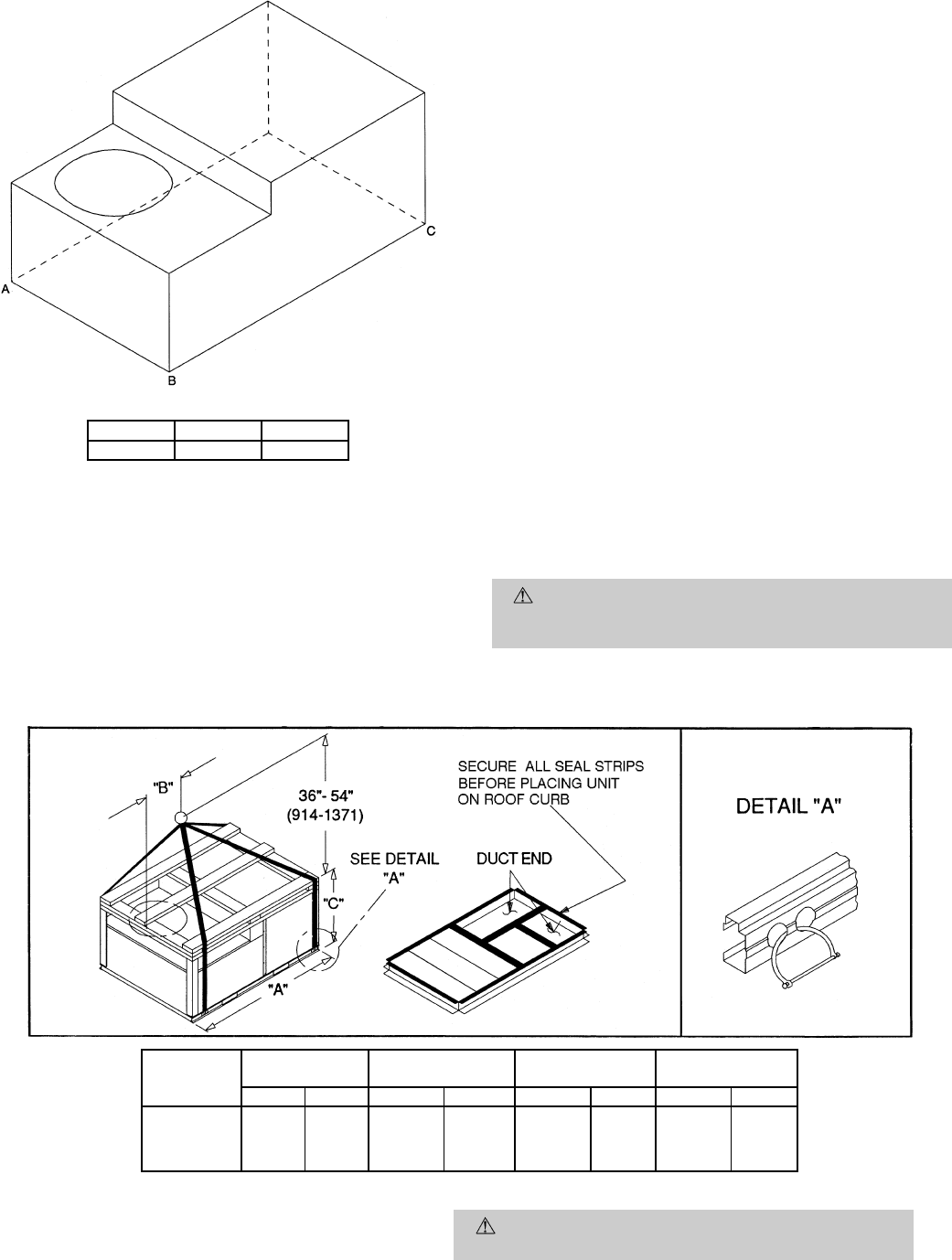
MAXIMUM ALLOWABLE DIFFERENCE (in.)
A-B B-C A-C
0.5 1.0 1.0
Fig. 5 — Unit Leveling Tolerances
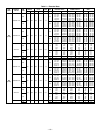
UNIT
MAX
WEIGHT
‘‘A’’ ‘‘B’’ ‘‘C’’
Lb Kg in. mm in. mm in. mm
558D036 415 188
73.69 1872 35.00 889 33.35 847
558D048 425 193
558D060 445 202
558D072 520 236
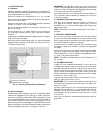
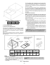
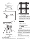
NOTES:
1. Dimension in ( ) is in millimeters.
2. Hook rigging shackles through holes in base rail, as shown in
detail ‘‘A.’’ Holes in base rails are centered around the unit
center of gravity. Use wooden top skid when rigging to pre-
vent rigging straps from damaging unit.
3. Weights do not include economizer. See Table 1 for econo-
mizer weights.
CAUTION: All panels must be in place when
rigging.
Fig. 6 — Rigging Details
—6—