


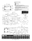
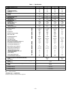
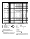
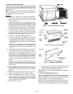
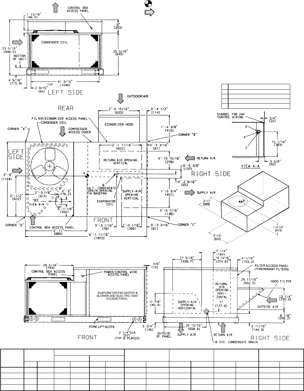
*Indicates horizontal center of gravity.
†Indicates vertical center of gravity.
NOTES:
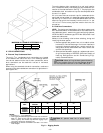
1. Dimensions in [ ] are in millimeters.
2. Center of gravity.
3. Direction of airflow.
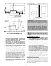
4. Ductwork to be attached to accessory roof curb only.
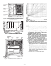
5. Minimum clearance (local codes or jurisdiction may prevail):
a. Bottom of basepan to combustible surfaces (when not using curb), 0 inches. On
horizontal discharge units with electric heat, 1 in. clearance to ductwork for 1 foot.
b. Condenser coil, for proper airflow, 36 in. one side, 12 in. the other. The side getting
the greater clearance is optional.
c. Overhead, 60 in. to assure proper condenser fan operation.
d. Between units, control box side, 42 in. per National Electrical Code (NEC).
e. Between unit and ungrounded surfaces, control box side, 36 in. per NEC.
f. Between unit and block or concrete walls and other grounded surfaces, control box
side, 42 in. per NEC.
g. Horizontal supply and return end, 0 inches.
6. With the exception of the clearances as stated in Notes 5a, b, and c, a removable
fence or barricade requires no clearance.
7. Units may be installed on combustible floors made from wood or class A, B, or C roof
covering material.
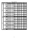
CONNECTION SIZES
A 1
1
⁄
8
Љ dia [28.6] field power supply hole
B
3
⁄
4
Љ-14 NPT condensate drain
C 1
3
⁄
8
Љ dia [35] power supply knockout
D 2Љ dia [50.8] power supply knockout
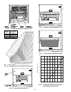
UNIT
STD UNIT
WEIGHT
ECONOMIZER WEIGHT
CORNER WEIGHT
(A)
CORNER WEIGHT
(B)
CORNER WEIGHT
(C)
CORNER WEIGHT
(D)
DURABLADE PARABLADE
Lb Kg Lb Kg Lb Kg Lb Kg Lb Kg Lb Kg Lb Kg
558D036 365 165.6 34 15.4 42 19.1 126 57.2 89 40.4 111 50.3 39 17.7
558D048 375 170.1 34 15.4 42 19.1 128 58.1 90 40.8 114 51.7 43 19.5
558D060 395 179.2 34 15.4 42 19.1 132 59.9 94 42.6 120 54.4 49 22.2
558D072 470 213.2 34 15.4 42 19.1 148 67.1 103 46.7 155 70.3 64 29.0
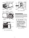
Fig. 2 — Base Unit Dimensions
—2—