


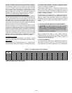
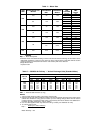
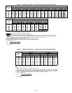
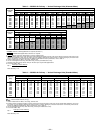
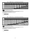
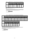
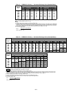
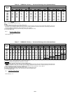
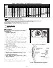
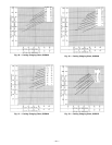
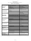
Table 18 — 558D072 Air Delivery — Horizontal Discharge Units (Standard Motor)
AIRFLOW
(Cfm)
STANDARD BELT DRIVE MOTOR
External Static Pressure (in. wg)
0.1 0.2 0.4 0.6 0.8 1.0 1.2 1.4 1.6
Rpm Watts Rpm Watts Rpm Watts Rpm Watts Rpm Watts Rpm Watts Rpm Watts Rpm Watts Rpm Watts
1800 765 487 821 532 923 638 1019 843 1099 883 1178 1031 1249 1182 1316 1353 1382 1526
1900 802 539 854 585 953 700 1046 835 1126 965 1201 1106 1274 1275 1338 1439 1402 1621
2000 840 600 888 646 984 771 1073 907 1154 1047 1226 1990 1297 1361 1363 1534 1424 1718
2100 878 669 923 716 1015 843 1101 981 1182 1140 1252 1292 1320 1456 1388 1639 1448 1831
2200 916 739 958 795 1046 924 1129 1072 1209 1241 1280 1404 1345 1569 1410 1744 1473 1945
2300 954 827 993 883 1079 1022 1160 1173 1237 1344 1309 1517 1372 1691 1434 1866 1496 2067
2400 993 916 1029 973 1112 1123 1190 1275 1264 1447 1336 1639 1400 1823 1459 1997 1519 2188
2500 1031 1022 1066 1081 1145 1241 1220 1396 1292 1569 1363 1770 1428 1962 1486 2145 1543 2335
2600 1070 1131 1103 1199 1179 1353 1251 1517 1322 1700 1390 1901 1456 2102 1514 2300 1569 2487
2700 1109 1258 1140 1318 1212 1482 1283 1656 1352 1849 1418 2041 1483 2257 1543 2462 — —
2800 1148 1396 1177 1465 1246 1621 1316 1805 1383 1997 1446 2188 1510 2403 ————
2900 1188 1543 1215 1604 1281 1770 1349 1962 1413 2154 1476 2352 1537 2562 ————
3000 1227 1700 1253 1770 1316 1936 1382 2136 1444 2317 1506 2529 ——————
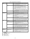
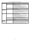
NOTES:
1. Boldface indicates field-supplied drive required. (See Note 7.)
2. indicates field-supplied motor and drive are required.
3.
indicates maximum usable watts of a factory-supplied motor.
4. Maximum usable watts input is 2120. Extensive motor and electrical testing on these units ensures that the full range of the motor can be
utilized with confidence. Using your fan motors up to the wattage ratings shown will not result in nuisance tripping or premature motor
failure. Unit warranty will not be affected. For additional information on motor performance, refer to Table 4.
5. Values include losses for filters, unit casing, and wet coils.
6. Use of a field-supplied motor may affect wire sizing. Contact your distributor to verify.
7. Standard motor drive range: 1070 to 1460. All other rpms require field-supplied drive.
8. To convert watts to bhp:
watts input x motor efficiency
bhp =
746
Motor efficiency = .84
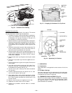
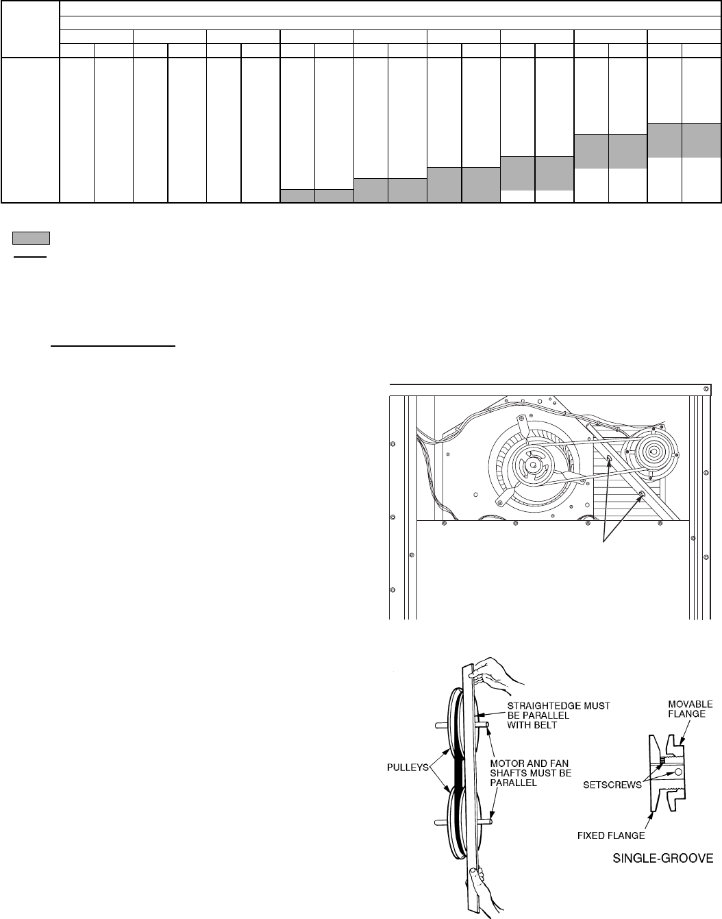
B. Belt Drive Motors
Fan motor pulleys are factory set for speed shown in Table 1.
To change fan speed:
1. Shut off unit power supply.
2. Loosen belt by loosening fan motor mounting nuts. See
Fig. 34.
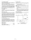
3. Loosen movable pulley flange setscrew (see Fig. 35).
4. Screw movable flange toward fixed flange to increase speed
and away from fixed flange to decrease speed. Increas-
ing fan speed increases load on motor. Do not exceed maxi-
mum speed specified in Table 1.
5. Set movable flange at nearest keyway of pulley hub and
tighten setscrew. (See Table 1 for speed change for each
full turn of pulley flange.)
To align fan and motor pulleys:
1. Loosen fan pulley setscrews.
2. Slide fan pulley along fan shaft.
3. Make angular alignment by loosening motor from
mounting.
To adjust belt tension:
1. Loosen fan motor nuts.
2. Slide motor mounting plate away from fan scroll for proper
belt tension (
1
⁄
2
-in. deflection with one finger).
3. Tighten motor mounting nuts.
4. Adjust lock bolt and nut on mounting plate to secure
motor in fixed position.
C. Ventilation Sequence
If unit is equipped with economizer, the damper will open to
the minimum position whenever the evaporator fan runs.
MOTOR MOUNTING
NUTS AND BOLTS
Fig. 34 — Belt-Drive Motor Mounting
Fig. 35 — Evaporator-Fan Pulley Adjustment
—27—