


9
TROUBLESHOOTING
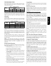
If the compressor fails to operate with a cooling call, Table 4 can be
used to verify if there is any damage to the compressor windings
causing system malfunction.
Table 4 – Winding Resistance
Winding
Winding resistance at 70_F +/ --- 20_F
(21.11_C +/--- 11.11_C)
187B024
187B036 /
180B036
187B048 187B060
Start (S ---C) 2.74 1.98 1.55 0.6
Run (R ---C) 0.8 0.75 0.48 0.49
Systems Communication Failure
If communication with the Evolution Control is lost with the user
interface, the control will flash the appropriate fault code. (See
Table 6) Check the wiring to the User Interface, indoor and
outdoor units.
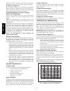
Model Plug
Each control board contains a model plug. The correct model plug
must be installed for or the system to operate properly (see Table
5).
Table 5 – Model Plug
Model
Number
Model Plug
Number
Pin Resistance
(k - Ohms)
Pin 1 - 4 Pin 2 - 3
187B024 Hk70EZ040 18K 75K
187B036 Hk70EZ042 18K 120K
180B036 Hk70EZ011 5.1K 150K
187B048 Hk70EZ044 18K 180K
187B060 Hk70EZ046 18K 270K
The model plug is used to identify the type and size of unit to the
control.
On new units, the model and serial numbers are input into the
board’s memory at the factory. If a model plug is lost or missing at
initial installation, the unit will operate according to the
information input at the factory and the appropriate error code will
flash temporarily.
An RCD replacement board contains no model and serial
information. If the factory control board fails, the model plug must
be transferred from the original board to the replacement board for
the unit to operate.
NOTE: The model plug takes priority over factory model
information input at the factory. If the model plug is removed after
initial power up, the unit will operate according to the last valid
model plug installed, and flash the appropriate fault code
temporarily.
Pressure Switch Protection
The outdoor unit is equipped with high and low pressure switches.
If the control senses the opening of a high or low pressure switch,
it will respond as follows:
1. De--energize the appropriate compressor contactor,
2. Keep the outdoor fan operating for 15 minutes,
3. Display the appropriate fault code (see Table 6).
4. After a 15 minute delay, if there is still a call for cooling and
the LPS or HPS is reset, the appropriate compressor contac-
tor is energized.
5. If LPS or HPS has not closed after a 15 minute delay, the
outdoor fan is turned off. If the open switch closes anytime
after the 15 minute delay, then resume operation with a call
for cooling.
6. If LPS or HPS trips 3 consecutive cycles, the unit operation
is locked out for 4 hours.
7. In the event of a high pressure switch trip or high pressure
lockout, check the refrigerant charge outdoor fan operation
and outdoor coil for airflow restrictions.
8. In the event of a low pressure switch trip or low pressure
lockout, check the refrigerant charge and indoor airflow.
Control Fault
If the outdoor unit control board has failed, the control will flash
the appropriate fault code. (See Table 6) The control board should
be replaced.
Brown Out Protection
If the line voltage is less than 187v for at least 4 seconds, the
appropriate compressor contactor and fan relay are de--energized.
Compressor and fan operation are not allowed until voltage is a
minimum of 190v. The control will flash the appropriate fault code
(see Table 6)
230 V Brown Out Protection Defeated:
The brownout feature can be defeated if needed for severe noisy
power conditions. This defeat should always be a last resort to
solving the problem. Defeat is available on the User Interface
setup screen (available with SYSTXBBUID01--C UI) or can be
initiated through the forced defrost pins for non--communicating
systems as follows:
The brownout toggle is accomplished by shorting the defrost pins
from power up with the OAT and OCT sensor connector removed.
After 3 seconds, the status of the force defrost short and the
OAT/OCT as open will be checked. If correct, then the brownout
will be toggled.
S Status code 6 shows the brownout is disabled.
S Status code 5 shows the brownout is active.
After the brownout defeat is set, power down and reinstall the
OAT/OCT sensor and remove the short from the forced defrost
pins. As long as the short on the forced defrost remains, the OAT
and OCT faults will not be cleared. The code will continue to be
flashed.
The control is shipped with the brownout active. The change in
status is remembered until toggled to a new status. A power
down/power up sequence will not reset the status. It may be
necessary to do the toggle twice to cycle to the desired state of the
defeat.
230V Line (Power Disconnect) Detection
If there is no 230v at the compressor contactor(s) when the indoor
unit is powered and cooling demand exists, the appropriate error
code is displayed (see Table 6). Verify that the disconnect is closed
and 230v wiring is connected to the unit.
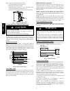
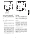
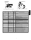
Compressor Voltage Sensing
The control board input terminals labeled VS and L2 (see Fig. 6)
are used to detect compressor voltage status, and alert the user of
potential problems. The control continuously monitors the high
voltage on the run capacitor of the compressor motor. Voltage
should be present any time the compressor contactor is energized,
and voltage should not be present when the contactor is
de--energized.
Contactor Shorted Detection
If there is compressor voltage sensed when there is no demand for
compressor operation, the contactor may be stuck closed or there is
a wiring error. The control will flash the appropriate fault code.
Compressor Thermal Cutout
If the control senses the compressor voltage after start--up, and is
then absent for 10 consecutive seconds while cooling demand
exists, the thermal protector is open. The control de--energizes the
compressor contactor for 15 minutes, but continues to operate the
outdoor fan.
The control Status LED will flash the appropriate code shown in
Table 6. After 15 minutes, with a call for low or high stage cooling,
the compressor contactor is energized. If the thermal protector has
not reset, the outdoor fan is turned off. If the call for cooling
continues, the control will energize the compressor contactor every
15 minutes. If the thermal protector closes, (at the next 15 minute
interval check), the unit will resume operation. If the thermal
187B / 180B