


11
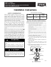
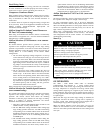
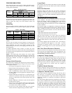
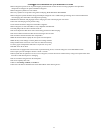
OAT Thermistor must be
lockedin place with spherical
nib end facingtowards the
front of the control box
Fig. 8 -- Outdoor Air Thermistor (OAT) Attachment
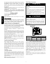
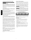
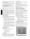
OCT Thermistormust be
securedtighton the liquid tube.
Fig. 9 -- Outdoor Coil Thermistor (OCT) Attachment
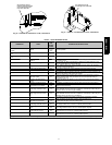
Table 6 – TROUBLESHOOTING
OPERATION FAULT
AMBER
LED
FLASH
CODE
POSS IBLE CAUSE A ND ACTION
Standby – no call for unit op-
eration
None
On so l-
id, no
flash
Normal operation
Low ---stage Cool/Heat Opera-
tion
None 1, pause Normal operation
High-stage Cool/Heat Opera-
tion
None 2, pause Normal operation
System Communications
Failure
16
Communication with user interface lost. Check wiring to User Interface, indoor
and outdoor units
Invalid Model P lug 25
Control does not detect a model plug or detects an invalid model plug. Unit
will not operate without correct model plug.
High Pressure Switch Open 31*
High---pressure switch trip. Check refrigerant charge, outdoor fan operation
and coils for airflow restrictions.
Low Pressure Switch Open 32* Low pressure switch trip. Check refrigerant charge and indoor air flow
Control Fault 45 Outdoor unit control board hasfailed. Control bo ard needs to be replaced.
Brown Out (230 v) 46
Line voltage < 187v for at l ea st 4 seconds. Compressor andf a n operation not
allowed until voltage>190v. Verify line voltage.
No 230v at Unit 47
There is no 230v at the contactor when indoor unit is powered an d cooling/
heating demand exists. Verify the disconnect is closed and 230v wiring is
connected to the unit.
Outdoor Air Temp Sensor
Fault
53
Outdoor air sensor notreading or outof range. Ohm out sensor and check
wiring.
Outdoor Coil Sensor Fault 55 Coil sensor not reading or out of range. Ohm out sensor and check wiring.
Thermistors out of range 56
Improper rela tionship between coil sensor and outdoor air sensor. Ohm out
sensorsand check wiring.
Low stage Thermal Cutout 71*
Compressor o peration detected then disappears while low---stage demand
exists. Possible causes are internal compressor overloadtrip or start relay and
capacitor held in circuit too long(if installed )
High stage Thermal Cutout 72*
Compressor o peration detected then disappears while high---stage demand
exists. Possible causes are internal compressor overloadtrip or start relay and
capacitor held in circuit too long (if installed)
Contactor Shorted 73
Compressor voltage sens ed when no d emand for c ompressor operation
exists. Contactor may be stuck closedor there is a wiringerror.
No 230V at Compressor 74
Compressor voltage not sensed when compressor should be starting. Contac-
tor may b e stuck open or there is a wiring error.
Low-stage Thermal L ockout 81
Thermal cutout occurs in three consecutive low/ high---stage cycle s.
low---stage lo cked out for 4 ho urs or until 24v power recycled.
High-stage Thermal Lock-
out
82
Thermal cutout o ccurs in three consecutive high/low---stage cycles.
high---stage locked out for 4 hours or until 24v power recycled.
Low Pressure Lockout 83
Low pressure swit ch trip has occurred during 3 consecutive cycles. Unit oper-
ation locked out for 4 hours or until 24v power recycled.
High Pressure Lockout 84
High pressure switch trip has occurred during 3 consecutive cycles. Unit oper-
ation locked out for 4 hours or until 24v power recycled.
* Sequence: Compressor contactor is de-energized and outdoor fan is energized for up to 15 minutes. If demand still exists, control will energize compressor.
187B / 180B