


3
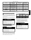
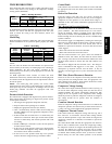
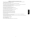
Table 1 – Accessory Usage
ACCESSORY
REQUIRED FOR
LOW --- AMBI ENT C OOLING
APPLICATIONS
(Below 55°F/12.8_C)
REQUIRED FOR LONG LINE
APPLICATIONS*
REQUIRED FOR SEA COAST
APPLICATIONS
(Within 2 miles/3.22 km )
Compressor Start Assist Kit No Yes No
Crankc ase Heater Standard Standard Standard
Evaporator F reeze Protect ion
Standard with Evolutiont Control
(Low Ambient n ot all owed with
non---communicating thermostat)
No No
Liquid---Line Solenoid Valve No No No
Low---Ambient Control
Standard with Ev olution Control
(Low ambient not allowed with
non---communicating thermostat)
No No
Puron Refrigera nt Balance Port Hard---
ShutOff TXV
Yes{
Yes{
Yes{
Support Feet Recommended No Recommended
Winter Start Control
Standard with Ev olution Control
(Low Ambient not all owed with
non---communicating thermostat)
No No
* For tubing set l engths between 80 and 200 ft. (24.38 and 60.96 m) horizontal or 35 ft. (10.7 m) vertical differential (total equivalent l ength), r efer to the Long
Line Guideline—Air Conditioners and Heat Pumps using Puron® Refrigerant.
{ Requiredon all indoor units. Standard on all new Puron refrigerant fan coilsand furnace coils.
Outdoor Unit Connected to Factory Approved Indoor
Unit
Outdoor unit contains correct system refrigerant charge for
operation with factory approved AHRI rated indoor unit when
connected by 15 ft. (4.57 m) of field--supplied or factory--accessory
tubing, and factory supplied filter drier. Check refrigerant charge
for maximum efficiency.
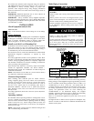
NOTE: If the indoor furnace coil width is more than the furnace
casing width, refer to the indoor coil Installation Instructions for
transition requirements.
!
WARNING
UNIT OPERATION AND SAFETY HAZARD
Failure to follow this warning could result in personal injury
or equipment damage.
PuronR refrigerant systems operate at higher pressures than
standard R--22 systems. Do not use R--22 service equipment
or components on PuronR refrigerant equipment.
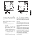
Refrigerant Tubing Connection Outdoor
Connect vapor and liquid tubes to fittings on vapor and liquid
service valves (see Table 2.) Use refrigerant grade tubing.
Sweat Connection
CAUTION
!
UNIT DAMAGE HAZARD
Failure to follow this caution may result in equipment
damage or improper operation.
Service valves must be wrapped in a heat--sinking material
such as a wet cloth while brazing.
Use refrigeration grade tubing. Service valves are closed from
factory and ready for brazing. After wrapping service valve with a
wet cloth, braze sweat connections using industry accepted
methods and materials. Consult local code requirements.
Refrigerant tubing and indoor coil are now ready for leak testing.
This check should include all field and factory joints.
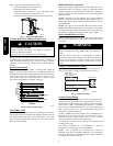
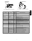
Table 2 – Refrigerant Connections and Recommended Liquid
and Vapor Tube Diameters (In.)
UNIT SIZE
LIQUID RATED VAPOR*
Connection
&Max.Tube
Diameter
Connection
Diameter
Tube
Diameter
024 3/8 3/4 3/4
036 3/8 7/8 7/8
048 3/8 7/8 1-1/8
060 3/8 7/8 1-1/8
* Units are rated with 25 ft. (7.6 m) of lineset. See Product Data sheet for
performance data when usingdifferent size and length linesets.
Notes:
1. Do not apply capillary tube or fixed orifice indoor coils to these units.
2. For Tubing Set lengths between 80 and 200 ft. (24.38 an d 60.96 m)
horizontal or 35 ft. (10.7 m) vertical differential 250 f t. (76.2 m) Total
Equivalent Length), refer to the Residential Piping and Longline Guide
line--- Air Conditioners andHeat Pumps using Puron refrigerant.
3. For alternate liquid line options on 18---42 size units, see Product Data or
Residential Piping and Application Guideline
Install Liquid--Line Filter Drier Indoor
CAUTION
!
UNIT DAMAGE HAZARD
Failure to follow this caution may result in equipment
damage or improper operation.
1. Installation of filter drier in liquid line is required.
2. Filter drier must be wrapped in a heat--sinking material
such as a wet cloth while brazing.
187B / 180B