


5
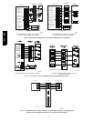
Final Wiring Check
IMPORTANT: Check factory wiring and field wire connections
to ensure terminations are secured properly. Check wire routing to
ensure wires are not in contact with tubing, sheet metal, etc.
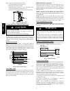
CompressorCrankcaseHeater
When equipped with a crankcase heater, furnish power to heater a
minimum of 24 hr before starting unit. To furnish power to heater
only, set thermostat to OFF and close electrical disconnect to
outdoor unit.
A crankcase heater is required if refrigerant tubing is longer than
80 ft. (24.38 m). Refer to the Application Guideline and Service
Manual Longline Section--Residential Split--System Air
Conditioners and Heat Pumps.
Airflow Setup for Evolution Control Furnace or
FE Fan Coil (communicating)
When using an Evolution User Interface, airflow is automatically
selected based on equipment size. See User Interface Installation
Instructions for available adjustments.
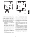
Airflow Selections (ECM Furnaces -- non commu-
nicating)
The ECM Furnaces provide blower operation to match the
capacities of the compressor during high and low stage cooling
operation. Tap selections on the furnace control board enable the
installing technician to select the proper airflows for each stage of
cooling. Below is a brief summary of the furnace airflow
configurations
1. The Y2 call for high stage cooling energizes the “Cool” tap
on the control board. The grey wire from cool tap is connec-
ted to tap 5 on the motor. Refer to the furnace Product Data
to find the corresponding airflow. If the airflow setting for
high cooling needs to be switched from tap 5 to a different
tap, jumper a connection from the cool tap to the desired tap
so that the Y2 signal is communicated via the cool tap to the
desired speed tap.
2. The Y1 call for low stage cooling energizes the “Fan” tap
on the control board. The red wire from the fan tap is con-
nected to tap 1 on the motor. Refer to the furnace Product
Data to find the corresponding airflow. If the airflow setting
for low cooling needs to be switched from tap 1 to a differ-
ent tap, jumper a connection from the Fan tap to the desired
tap so that the Y1 signal is communicated via the Fan tap to
the desired speed tap. The Y1 setting will also govern the
continuous fan airflow for the furnace.
Refer to the literature for the furnace for further details.
Airflow Selection for Variable Speed Furnaces
(non--communicating)
The variable speed furnaces provide blower operation to match the
capacities of the compressor during high and low stage cooling
operation. The furnace control board allows the installing
technician to select the proper airflows for each stage of cooling.
Below is a summary of required adjustments. See furnace
installation instructions for more details:
1. Turn SW1----5 ON for 400 CFM/ton airflow or OFF for 350
CFM/ton airflow. Factory default is OFF.
2. The A/C DIP switch setting determines airflow during high
stage cooling operation. Select the A/C DIP switch setting
corresponding to the available airflow shown in the furnace
Installation Instructions that most closely matches the re-
quired airflow shown in the air conditioning Product Data
for HIGH speed.
3. The CF DIP switch setting determines airflow during low
stage cooling operation. Select the CF DIP switch setting
corresponding to the available airflow shown in the furnace
installation instructions that most closely matches the re-
quired airflow shown in the air conditioning Product Data
for LOW speed. If a higher or lower continuous fan speed is
desired, the continuous fan speed can be changed using the
fan switch on the thermostat. Refer to the furnace Installa-
tion Instructions for details of how to use this feature.
Airflow Selection for FV4C Fan Coils (non--com-
municating)
The FV4 provides high-- and low--stage blower operation to match
the capacities of the compressor at high-- and low--stage.
To select recommended airflow, refer to the FV4C Installation
Instructions. The FV4C utilizes an Easy Select control board that
allows the installing technician to select proper airflows. This fan
coil has an adjustable blower--off delay factory set at 90 sec. for
high-- and low--stage blower operation.
When using a communicating control with the fan coil or the
furnace, dip--switch adjustments are not necessary. The outdoor
unit configuration and the indoor airflows are determined by
communicating control setup.
Start--Up
CAUTION
!
UNIT OPERATION AND SAFETY HAZARD
Failure to follow this caution may result in personal injury,
equipment damage or improper operation.
S Do not overcharge system with refrigerant.
S Do not operate unit in a vacuum or at negative pressure.
S Compressor dome temperatures may be hot.
CAUTION
!
PERSONAL INJURY HAZARD
Failure to follow this caution may result in personal injury.
Wear safety glasses, protective clothing, and gloves when
handling refrigerant and observe the following:
S Front seating service valves are equipped with Schrader
valves.
SYSTEM FUNCTIONS AND SEQUENCE
OF OPERATION
The 180B / 187B models utilize either an Evolution
Communicating User Interface or a 2-stage cooling indoor
thermostat. With a call for first stage cooling, the outdoor fan and
low-stage compressor are energized. If low-stage cannot satisfy
cooling demand, high-stage is energized by the second stage of
indoor thermostat. After second stage is satisfied, the unit returns to
low-stage operation until first stage is satisfied or until second stage
is required again.
When both first stage and second stage cooling are satisfied, the
compressor will shut off. When a 2-stage unit is operating at
low-stage, system vapor (suction) pressure will be higher than a
standard single-stage system or high-stage operation.
When the outdoor ambient is more than 100_F (37.8_C), the
outdoor fan will continue to run for one minute after compressor
shuts off. this reduces pressure differential for easier starting in the
next cycle.
187B / 180B