


2
The outdoor unit contains system refrigerant charge for operation
with AHRI rated indoor unit when connected by 15 ft. (4.57 m) of
field--supplied or factory accessory tubing. For proper unit
operation, check refrigerant charge using charging information
located on control box cover and/or in the Check Charge section of
this instruction.
IMPORTANT: Maximum liquid--line size is 3/8--in. OD for all
residential applications including long line.
IMPORTANT: Always install the factory--supplied liquid--line
filter drier. If replacing the filter drier, refer to Product Data Digest
for appropriate part number. Obtain replacement filter driers from
your distributor or branch.
INSTALLATION
Check Equipment and Job Site
UNPACK UNIT
Move to final location. Remove carton taking care not to damage
unit.
Inspect Equipment
File claim with shipping company prior to installation if shipment
is damaged or incomplete. Locate unit rating plate on unit corner
panel. It contains information needed to properly install unit.
Check rating plate to be sure unit matches job specifications.
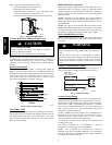
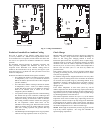
Install on a Solid, Level Mounting Pad
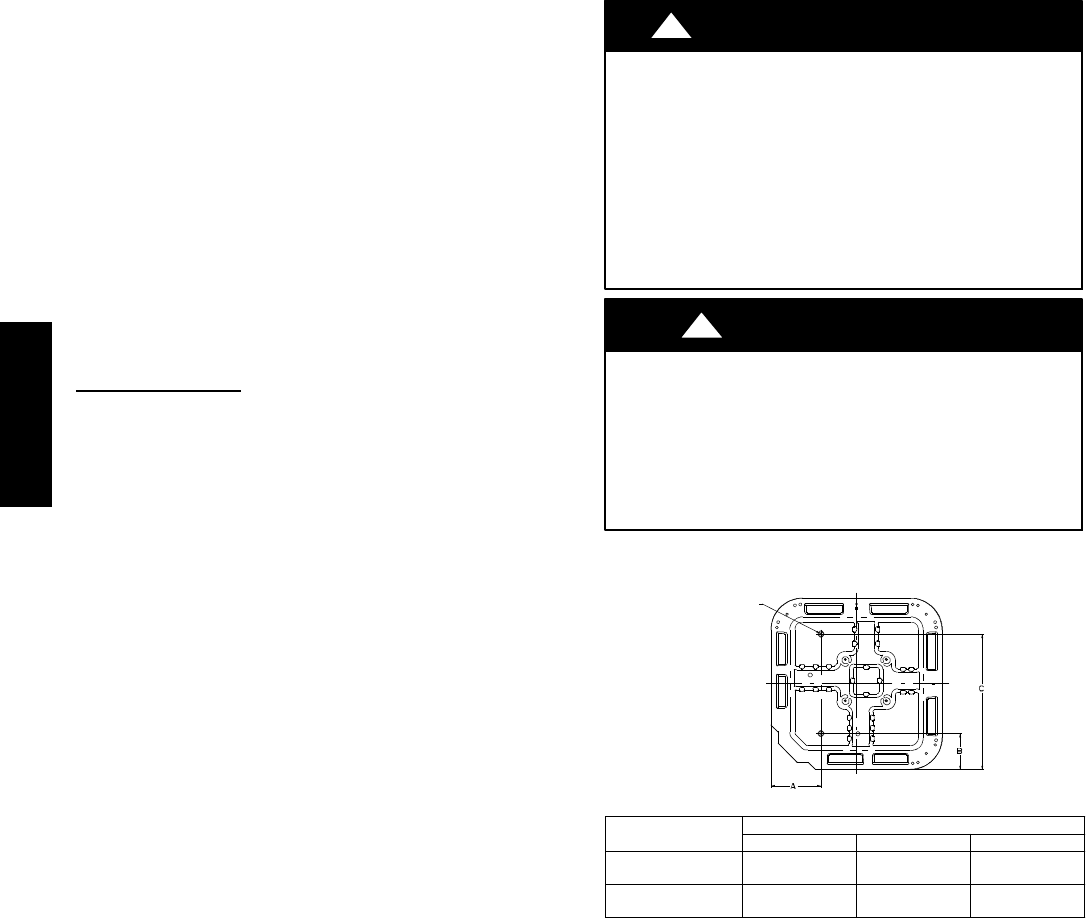
If conditions or local codes require the unit be attached to pad, tie
down bolts should be used and fastened through knockouts
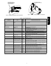
provided in unit base pan. Refer to unit mounting pattern in Fig. 2
to determine base pan size and knockout hole location.
For hurricane tie downs, contact local distributor for details and PE
(Professional Engineer) certification, if required by local
authorities.
On rooftop applications, mount on level platform or frame. Place
unit above a load--bearing wall and isolate unit and tubing set from
structure. Arrange supporting members to adequately support unit
and minimize transmission of vibration to building. Consult local
codes governing rooftop applications.
Roof mounted units exposed to winds may require wind baffles.
Consult the Application Guideline and Service Manual --
Residential Split System Air Conditioners and Heat Pumps for
wind baffle construction.
NOTE: Unit must be level to within ±2_ (±3/8 in./ft,±9.5 mm/m.)
per compressor manufacturer specifications.
Clearance Requirements
When installing, allow sufficient space for airflow clearance,
wiring, refrigerant piping, and service. Allow 24 in. (609.6 mm)
clearance to service end of unit and 48 in. (1219.2 mm) (above
unit. For proper airflow, a 6--in. (152.4 mm) clearance on 1 side of
unit and 12--in. (304.8 mm) on all remaining sides must be
maintained. Maintain a distance of 24 in. (609.6 mm) between
units. Position so water, snow, or ice from roof or eaves cannot fall
directly on unit.
On rooftop applications, locate unit at least 6 in. (152.4 mm) above
roof surface.
Operating Ambient
The minimum outdoor operating ambient in cooling mode is 55_F
(12.78_C) without low ambient cooling enabled in the Evolution
Control, and the maximum outdoor operating ambient in cooling
mode is 125_F (51.67_C). At line voltage of 208v (or below, and
outdoor ambient of 120_F (48.9_C) (and above), the compressor
operates in low stage.
NOTE: This product is approved for low ambient cooling if used
with a communicating User Interface.
Make Piping Connections
!
WARNING
PERSONAL INJURY AND ENVIRONMENTAL
HAZARD
Failure to follow this warning could result in personal injury
or death.
Relieve pressure and recover all refrigerant before system
repair or final unit disposal. Use all service ports and open
all flow--control devices, including solenoid valves.
Federal regulations require that you do not vent refrigerant
to the atmosphere. Recover during system repair or final
unit disposal.
CAUTION
!
UNIT DAMAGE HAZARD
Failure to follow this caution may result in equipment
damage or improper operation.
If ANY refrigerant tubing is buried, provide a 6--in (152.4
mm) vertical rise at service valve. Refrigerant tubing lengths
up to 36--in (914.4 mm) may be buried without further
special consideration. Do not bury lines more than 36--in.
(914.4 mm).
3/8---in. (9.53 mm)Dia.
Tiedown Knockouts in
Basepan(2) Places
View From Top
UNIT BASE PAN
Dimension i n. (mm)
TIEDOWN KNOCKOUT LOCATIONS in. (mm)
A B C
31–1/2 X 31–1/ 2
(800 X 800)
9–1/8 (231.8) 6–9/16 (166.7) 24–11/16 (627.1)
35 X 35
(889 X 889)
9–1/8 (231.8) 6–9/16 (166.7) 28–7/16 (722.3)
A05177
Fig. 2 -- Tiedown Knockout Locations
Outdoor units may be connected to indoor section using accessory
tubing package or field--supplied refrigerant grade tubing of correct
size and condition. Rated tubing diameters shown in Table 2 are
recommended up to 80 ft. (24.38 m). See Product Data for
acceptable alternate vapor diameters and associated capacity losses.
For tubing requirements beyond 80 ft. (24.38 m), substantial
capacity and performance losses can occur. Following the
recommendations in the Residential Piping and Longline
Guideline will reduce these losses. Refer to Table 2 for field tubing
diameters. Refer to Table 1 for accessory requirements.
There are no buried--line applications greater than 36--in. (914.4
mm) allowed.
If refrigerant tubes or indoor coil are exposed to atmosphere, they
must be evacuated to 500 microns to eliminate contamination and
moisture in the system.
187B / 180B