


10
cutout trips for three consecutive cycles, then unit operation is
locked out for 4 hours and the appropriate fault code is displayed.
No 230V at Compressor
If the compressor voltage is not sensed when the compressor
should be starting, the appropriate contactor may be stuck open or
there is a wiring error. The control will flash the appropriate fault
code. Check the contactor and control box wiring.
Troubleshooting units for proper switching
between low & high stages
Check the suction pressures at the service valves. Suction pressure
should be reduced by 3--10% when switching from low to high
capacity.
NOTE: The liquid pressures are very similar between low and
high stage operation so liquid pressure should not be used for
troubleshooting.
Compressor current should increase 20--45% when switching from
low to high stage. The compressor solenoid, when energized in
high stage, should measure 24vac. When the compressor is
operating in low stage the 24v DC compressor solenoid coil is
de--energized. When the compressor is operating in high stage, the
24v DC solenoid coil is energized. The solenoid plug harness that
is connected to the compressor has an internal rectifier that
converts the 24v DC signal to 24v AC.
NOTE: DO NOT INSTALL A PLUG WITHOUT AN
INTERNAL RECTIFIER.
Unloader Test Procedure
The unloader is the compressor internal mechanism, controlled by
the DC solenoid, that modulates between high and low stage. If it
is suspected that the unloader is not working, the following
methods may be used to verify operation.
1. Operate the system and measure compressor amperage.
Cycle the unloader on and off at 30 second plus intervals at
the UI (from low to high stage and back to low stage). Wait
5 seconds after staging to high before taking a reading. The
compressor amperage should go up or down at least 20 per-
cent.
2. If step one does not give the expected results, remove the
solenoid plug from the compressor and, with the unit run-
ning and the UI (or Thermostat) calling for high stage, test
the voltage output at the plug with a DC voltmeter. The
reading should be 24 volts DC.
3. If the correct DC voltage is at the control circuit molded
plug, measure the compressor unloader coil resistance. The
resistance should be 32 to 60 ohms depending on com-
pressor temperature. If the coil resistance is infinite, much
lower than 32 ohms, or is grounded, the compressor must
be replaced.
MAJOR COMPONENTS
2--Stage Control
The 2--stage control board controls the following functions:
— Compressor high and low stage operation
— Outdoor fan motor operation
— Low ambient cooling
— Compressor external protection
— Pressure switch monitoring
— Time delays
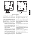
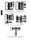
Field Connections
On models with non--communicating (non--Evolution) system, the
2--stage control receives 24vac low--voltage control system inputs
through the R, C, Y1, and Y2 connections located at the bottom of
the control board (see Fig. 6). The OD units can be controlled
using a standard 2--stage thermostat or Evolution User Interface.
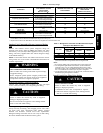
2--Stage Compressor
The 2--stage compressor contains motor windings that provide
2--pole (3500 RPM) operation. Refer to Table 4 for correct
winding resistance.
Compressor Internal Relief
The compressor is protected by an internal pressure relief (IPR)
which relieves discharge gas into compressor shell when
differential between suction and discharge pressures exceeds 550 --
625 psi The compressor is also protected by an internal overload
attached to motor windings.
Compressor Control Contactor
The contactor has a 24 volt coil. The electronic control board
controls the operation of the appropriate contactor.
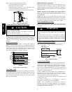
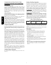
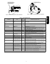
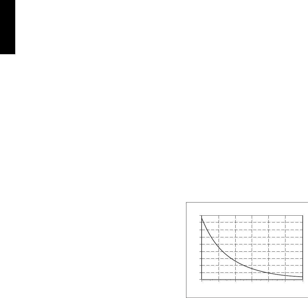
TEMPERATURE THERMISTORS
Thermistors are electronic devices which sense temperature. As the
temperature increases, the resistance decreases. Thermistors are
used to sense outdoor ambient (OAT) and coil temperature (OCT).
Refer to Fig. 7 for resistance values versus temperature. If the
outdoor ambient or coil thermistor should fail, the control will
flash the appropriate fault code (see Table 6.)
IMPORTANT: Outdoor air thermistor and coil thermistor are
factory mounted in the final locations. Check to insure thermistors
are mounted properly per Fig. 8 and Fig. 9.
Thermistor Sensor Comparison
The control continuously monitors and compares the outdoor air
temperature sensor and outdoor coil temperature sensor to ensure
proper operating conditions. The comparison is:
— If the outdoor air sensor indicates 10_F (5.56_C) warmer
than the coil sensor (or) the outdoor air sensor indicates
20_F(11.11_C) cooler than the coil sensor, the sensors
are out of range.
— If the sensors are out of range, the control will flash the
appropriate fault code as shown in Table 6.
— The thermistor comparison is not performed during low
ambient cooling or defrost operation.
Failed Thermistor Default Operation
Factory defaults have been provided in the event of failure of
outdoor air thermistor and/or coil thermistor.
If the OAT sensor should fail, low ambient cooling will not be
allowed and the one minute outdoor fan--off delay will not occur.
If the OCT sensor should fail, low ambient cooling will not be
allowed.
OAT Thermistor must be locked in place with spherical nib end
facing towards the front of the control box
0
10
20
30
40
50
60
70
80
90
0
(-17.77)
20
(-6.67)
40
(4.44)
60
(15.56)
80
(26.67)
100
(37.78)
120
(48.89)
TEMPERATURE °F (°C)
RESISTANCE (KOHMS)
THERMISTOR CURVE
A08054
Fig. 7 -- Resistance Values Versus Temperature
187B / 180B