


11
Express® Lavatory System SS-Series
Installation Instructions - For Service Only SS-2/IR/STD, SS-2/IR/JUV
Bradley Corporation • 215-1243 Rev. D; EN 03-813 5/11/04
Installation Instructions
continued . . .
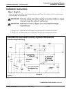
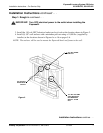
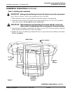
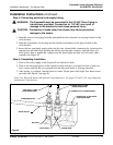
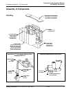
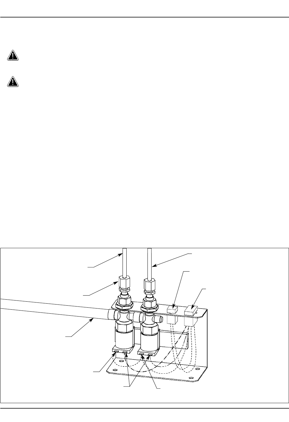
Step 5: Connecting electrical and supply tubing
WARNING: The Express® must be connected to the 24 VAC Class II plug-in
transformer provided. Connection to 110 VAC can result in
damage to the electronics and cause personal injury.
CAUTION: Connection of leads other than shown may cause permanent
damage to the sensor.
1. Snap the sensor circuit plug from the sprayhead into the solenoid circuit plug located on the
valve bracket.
2. Snap the transformer circuit plug into the female transformer circuit plug located on the
valve bracket.
3. Insert the two sprayhead supply tubes into the two solenoid tube connectors by loosening the
compression nut and firmly pushing the tubing into the tube connector until the tubes are
fully seated, then re-tighten the compression nut (hand-tight and then two full turns with a
wrench) (see Figure 8).
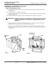
Step 6: Completing installation
1. Turn on the water supply to the Express® and check for leaks.
2. Turn on the electrical power to the electrical outlet and pass your hand in front of each sta-
tion’s sensor until all the air is purged from the lines and water is flowing smoothly.
3. After testing is complete, reinstall panel to frame. Fasten panel with eight Torx-head screws
provided (see Figure 3 on page 8).
Note: For Express® units with optional soap dispensers, see pages 12 and 13 for soap dispenser
maintenance instructions.
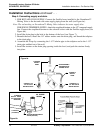
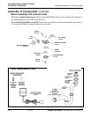
Figure 8
CONNECTOR TO SOLENOID
FROM SPRAYHEAD
CONNECTOR TO TRANSFORMER
WHITE WIRE
RED WIRE
GREEN WIRE
RED SUPPLY TUBE
(FROM SPRAYHEAD)
GREEN SUPPLY TUBE
(FROM SPRAYHEAD)
COMPRESSION NUT
WATER SUPPLY