


10
Express® Lavatory System SS-Series
SS-2/IR/STD, SS-2/IR/JUV Installation Instructions - For Service Only
5/11/04 Bradley Corporation • 215-1243 Rev. D; EN 03-813
Installation Instructions
continued . . .
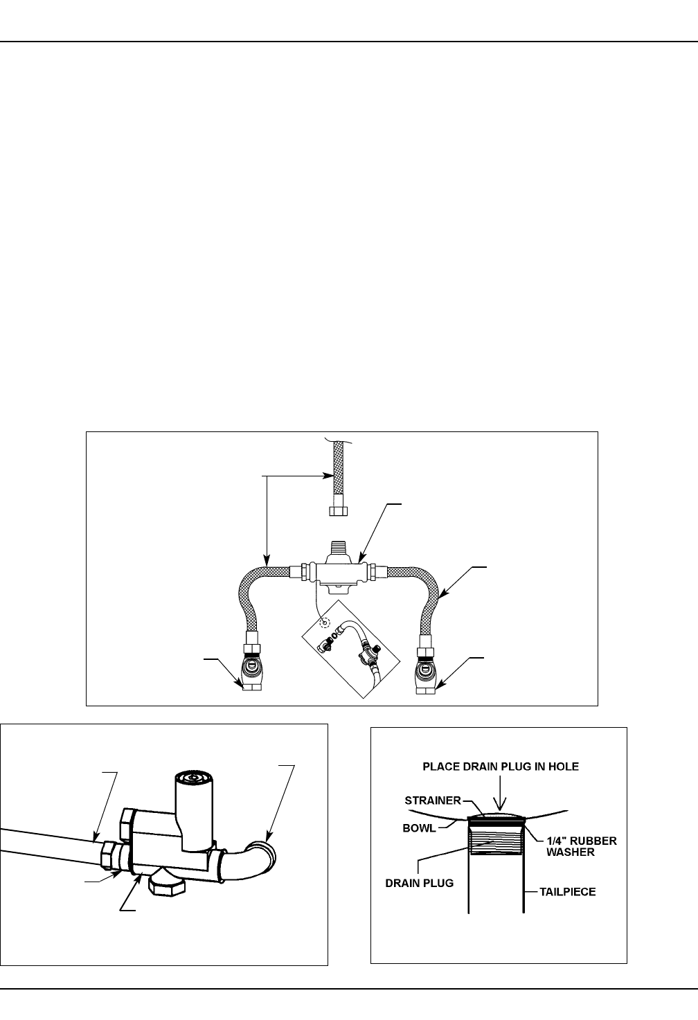
Step 4: Connecting supply and drain
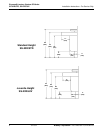
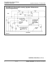
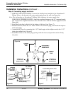
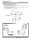
1. FOR HOT AND COLD SUPPLY: Connect the flexible hoses installed to the Vernatherm™
Mixing Valve to the hot and cold water supply piping from the wall (see Figure 6a).
Note: The red marking on Vernatherm™ Mixing Valve indicates hot water supply inlet.
FOR SINGLE TEMPERED SUPPLY: Attach the stop/check/strainer to the 1/2" tempered supply
line. Connect the stop/check/strainer to the solenoid valves with the flexible supply hose (see
Figure 6b).
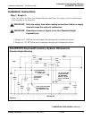
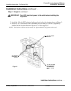
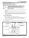
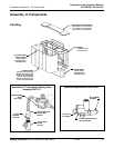
2. Install the drain plug in the hole in the bottom of the bowl (see Figure 7).
3. Beneath the bowl, install the 1/4" rubber washer onto the drain plug, and thread the tailpiece
to the drain plug.
4. Assemble the P-trap by connecting the 1-1/2" tubular pipe to the tailpiece and to the 1-1/2"
drain pipe stubbed out of the wall.
5. Install the strainer on the drain plug opening inside the bowl, and push the strainer firmly
into place.
Figure 7
Figure 6a
FLEXIBLE
SUPPLY
HOSE
VERNATHERM™
THERMOSTATIC
MIXING VALVE
FLEXIBLE
SUPPLY
HOSE
CONNECT TO
1/2" NPT COLD
WATER SUPPLY
CONNECT TO
1/2" NPT HOT
WATER SUPPLY
FLEXIBLE
SUPPLY HOSE
(TO SOLENOID
BRACKET)
Figure 6b
STOP/STRAINER/CHECK
VALVE (S60-003)
90° ELBOW
169-639
1/2 NIPPLE
(113-006DJ)