


58
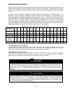
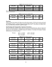
Table 20. (FM) Combustion Fan Motor.
Wire Color Voltage Resistance
Connector
No.
Pin
Nos.
Red-Black 6-45 VDC n/a E1 1-2
White-Black 5-10 VDC 9.2-9.4k ohms E1 2-4
Yellow-Black 11-13 VDC 3.5-3.9k ohms E1 2-3
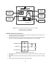
Set your meter to the hertz scale. Reading across the white and black wires at terminals 2 and 4 you should read
between 60 and 420 hertz.
Table 21. Thermal Fuse / Overheat Switch.
Wire Color Voltage Resistance
Connector
No.
Pin
Nos.
Red-Red 11-13 VDC Below 1 ohms
F6
H1
F6-
H12
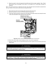
Flame Rod:
Place one lead of your meter to the flame rod and the other to ground. With the unit running, you should
read between 5-150 VAC. Set your meter to micro-amp scale and series your meter in line with the flame
rod. You should read 1 micro-amp or greater for proper flame circuit. In the event of low flame circuit,
remove the flame rod and check for carbon or damage.
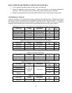
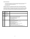
Heat Exchanger and Outgoing Water Temperature Thermistors:
Check all Thermistors by inserting meter leads into each end of the thermistor plug. Set your meter to the
20k scale and read resistance. Applying heat to the thermistor bulb should decrease the resistance.
Applying ice to the thermistor bulb should increase the resistance. See below for examples of typical
temperatures and resistance readings.
Example: 59ºF = 11.4-14kΩ 140ºF = 2.2-2.7kΩ
86ºF = 6.4-7.8kΩ 221ºF = 0.6-0.8kΩ
113º = 3.6-4.5kΩ
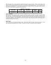
Table 22. Outgoing Water Thermistor.
Wire Color Voltage Resistance
Connector
No.
Pin
Nos.
White-White n/a
See example
above
F5 3-4
Table 23. Heat Exchanger Temperature Thermistor.
Wire Color Voltage Resistance
Connector
No.
Pin
Nos.
Pink-White n/a
See example
above
F4 3-11
Table 24. Intake Air Thermistor (Indoor Model Only).
Wire Color Voltage Resistance
Connector
No.
Pin
Nos.
Orange-White n/a
See example
above
F3 3-12
Table 25. Surge Protector.
Wire Color Voltage Resistance
Connector
No.
Pin
Nos.
Black-White 108-132 VAC n/a D2 1-3
Blue-Brown 108-132 VAC n/a D1 1-3