


11
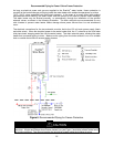
MOUNT WATER HEATER ON THE WALL
Determine the proper height and location for the water heater to be installed. Consider the venting
system, as well as the water and gas connections. Allow enough room for servicing the water heater and
maintain the clearances from combustible materials. The water heater is supported on the wall by means
of a top and bottom slotted angle bracket. For convenience, the center hole of the bracket is slotted so
that a center screw may be first installed in the wall for hanging the water heater on the wall. Two more
screws are then added on the ends of the bracket to secure the water heater. Wall anchors should be
used for the bracket holes unless the bracket lines up with a stud. As an alternative, a suitable piece of
plywood may be cut to span the wall studs and the brackets fastened to the plywood. Make sure the
anchors are rated to support the 55 pound (25 kg) weight of the water heater.
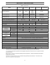
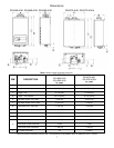
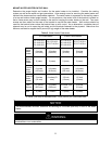
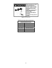
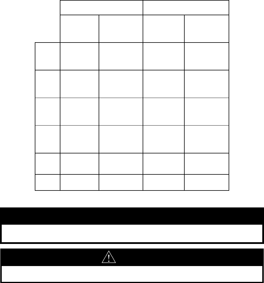
Table 3. Water Heater Clearances.
*4 inches (102 mm) for enclosed area; 1 inch (26 mm) for unenclosed area
to Combustibles to Non-Combustibles
TG-150I-N(X)
TG-180I-N(X)
TG-199I-N(X)
TG-237I-N(X)
TG-237I-N(X)A
TG-150I-N(X)
TG-180I-N(X)
TG-199I-N(X)
TG-237I-N(X)A
TG-237I-N(X)A
Top of
Water
Heater
6 inches
(152 mm)
12 inches
(305 mm)
2 inches
(51 mm)
2 inches
(51 mm)
Back of
Water
Heater
0 (zero) 0 (zero) 0 (zero) 0 (zero)
Front of
Water
Heater
6 inches
(152 mm)
24 inches
(610 mm)
6 inches
(152 mm)
24 inches
(610 mm)
Sides of
Water
Heater
2 inches
(51 mm)
2 inches (51
mm)
1/2 inch
(13 mm)
1/2 inch
(13 mm)
Floor/
Ground
12 inches
(305 mm)
12 inches
(305 mm)
12 inches (305
mm)
2 inches
(51 mm)
Vent 0 (zero) 4 inches * 0 (zero) 0 (zero)
WARNING
For all closet installations, follow the minimum clearances to combustibles whether the closet door is
combustible or non-combustible.
The recommended minimum clearance for servicing is 24 inches (608 mm) in front of the water
heater.
NOTICE