


56
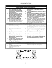
6. Mount the control to the wall using the holes drilled and with the screws supplied. Note: Plastic
wall anchors may be required if the control is not located over a stud when mounting on
wallboard.
Note: If the cable cannot be run inside the wall cavity, then the plastic knockout should be removed from
the top or bottom of the control to allow flush mounting with the wall.
7. Disconnect the power from the water heater and remove the front cover.
8. Remove the plastic cover from the PCB and electrical connections.
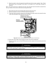
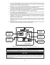
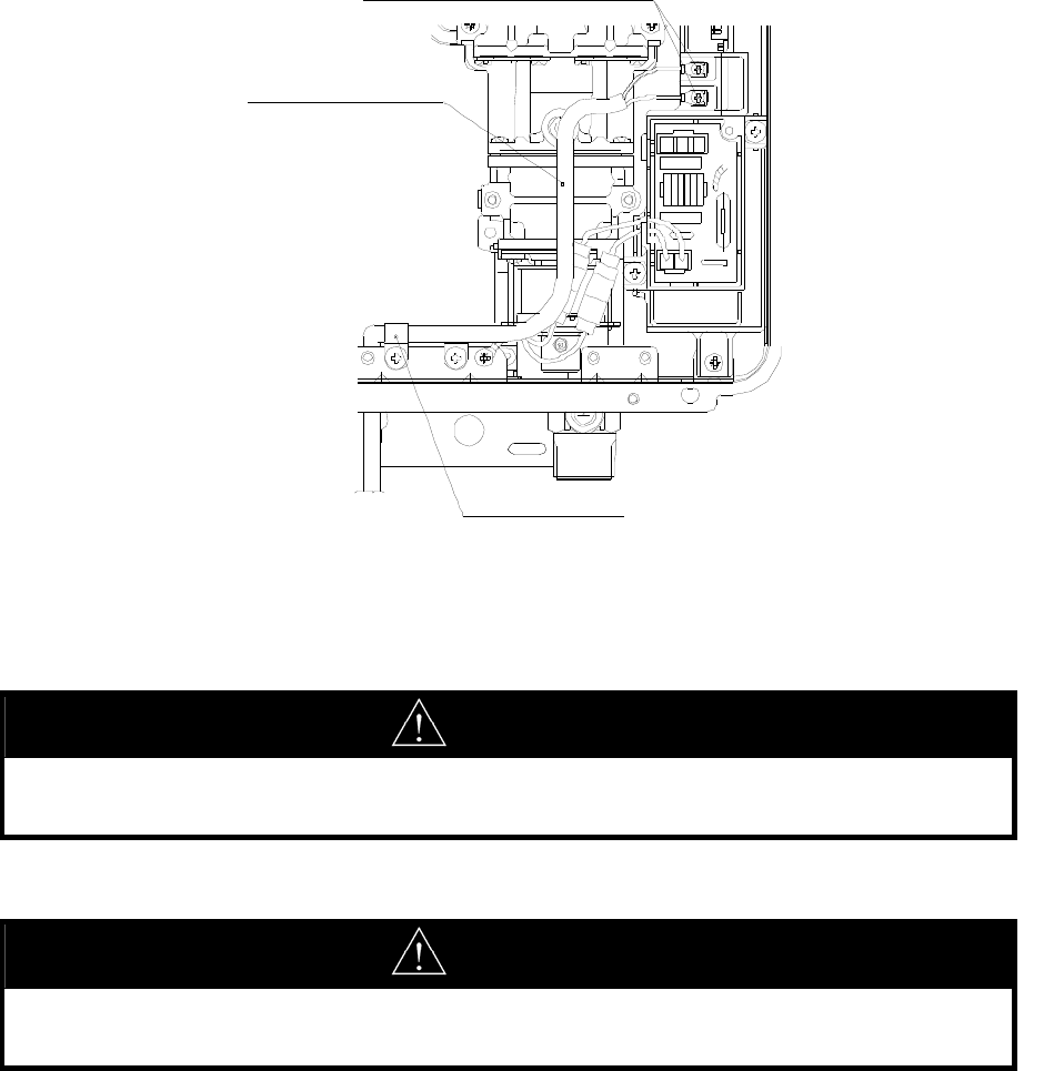
9. Thread the cable through the access hole at the base of the water heater and connect the wires
to the control terminals on the right hand side of the PCB.
10. Secure the control cable using the clamp provided in the control compartment.
11. Replace the plastic cover over the PCB terminals and then replace the front control panel of the
water heater.
WARNING
Do not attempt to connect the remote controls with the power on to the water heater. There is 120
volt terminals and wiring next to the remote control connections inside the unit. All servicing and
wiring must be performed by a qualified installer.
WARNING
When the water heater or remotely located remote control is used in public use applications, it shall
be installed in a location where it cannot be adjusted by the public (i.e. a maintenance room or
manager’s office). Unauthorized adjustments may result in scalding conditions.
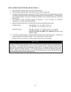
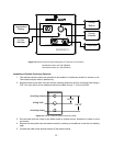
CABLE CLAMP
REMOTE
CONTROL CABLE
REMOTE CONTROL
CONNECTION TERMINALS
Figure 46. Illustration Showing Where to Connect Remote Control Harness.