


25
Vent pipes serving power vented appliances are classified by building codes as “vent connectors.”
Required clearances from combustible materials must be provided in accordance with information in this
manual under Location of Water Heater and Clearances, as well as the National Fuel Gas Code and local
codes.
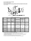
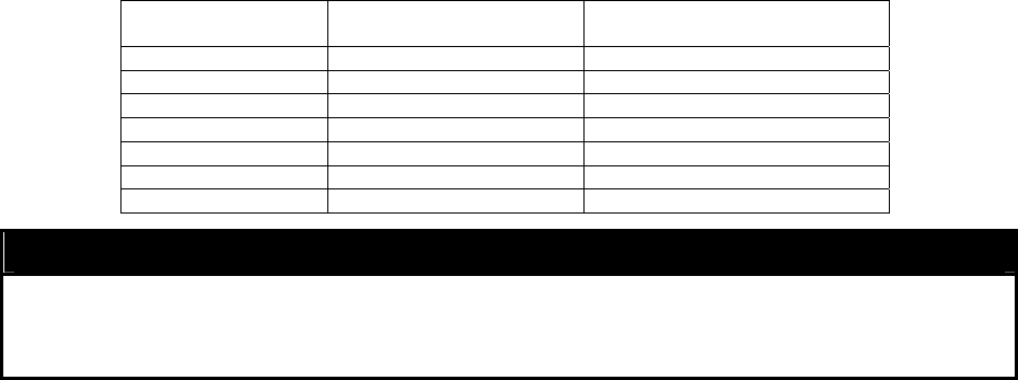
Table 7. Venting Table - Examples of Maximum Venting Distances.
Maximum Straight
Pipe Distance
Number of 90º Elbows
Maximum Total Equivalent
Length of Vent Pipe
41 ft (12.5 m) 0 41 ft (12.5 m)
35 ft (10.7 m) 1 41 ft (12.5 m)
29 ft (8.8 m) 2 41 ft (12.5 m)
23 ft (7.0 m) 3 41 ft (12.5 m)
17 ft (5.2 m) 4 41 ft (12.5 m)
11 ft (3.4 m) 5 41 ft (12.5 m)
5 ft (1.5 m) 6 41 ft (12.5 m)
NOTICE
Each 90º elbow is equivalent to 6 ft (1.8 m) in straight vent pipe length. Each 45 degree elbow is
equivalent to 1.5 ft (0.46 m) in straight pipe length. The total maximum equivalent vent pipe distance
cannot exceed 41 feet (12.5 m). The condensate collector must be used if the venting system height
is more than 5 ft (1.52 m) above the water heater.
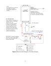
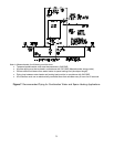
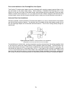
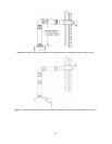
VENTING SYSTEM LAYOUT
Refer to the preceding illustration and location requirements for location of the vent terminal and also
local and state codes. In the absence of local codes, refer to the latest edition of the National Fuel Gas
Code ANSI Z223.1/NFPA 54. Keep the venting system as short as possible and keep the number of
elbows used to a minimum. The water heater may be vented directly through the wall (horizontally) or
vertically through the roof. In all cases, the maximum equivalent length of vent pipe allowed is 41 feet
(12.5 m). To calculate the total equivalent feet of vent pipe use the following formula:
D = L + (EL90 x 6) + (EL 45 x 1.5) For Length in Feet
D = L + (EL90 x 1.83) + (EL45 x 0.46) For Length in Meters
D = Total Equivalent Length of Venting System
L = Length of Straight Section of Vent / Air Intake Pipe (in feet)
EL90 = Number of 90º Elbows.
EL45 = Number of 45º Elbows
The venting table above provides examples of maximum venting distances with various elbow
combinations.
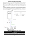
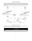
The Bradford White EverHot
TG model series has dedicated venting system components, which must
be ordered separately. Review the “Venting System Installation Instructions” and the venting components
later in this manual to determine the venting system layout and parts required. A Standard Vent Kit is
available for outside through the wall venting installations. The Standard Vent Kit consists of: one 90
discharge adapter and one horizontal vent termination kit. If this type of vent installation is not possible,
contact a venting supplier listed in this manual for additional venting components illustrated at the back of
this instruction manual.
If the vent termination height above the water heater exceeds 5 feet (1.5 m), the condensate collector
(integrated into the water heater’s vent connection on the top of the water heater) will be required to
collect condensate from the vent pipe. The condensate collector has a 5/8” outside diameter male metal
tube to connect to a condensate trap (loop) before being routed to a suitable drain.
VENTING SYSTEM INSTALLATION
Reference the preceding section and venting components illustrations at the end of this manual to
determine the parts required for your particular venting system installation. The required venting
component parts are available from the suppliers listed in this manual. Use the Venting System
Installation Instructions supplied with the venting components for detailed instructions on putting together
the venting components.