


29
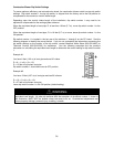
Combustion Blower Dip Switch Settings
To assure optimum efficiency and reduced noise levels, the combustion blower switch has two dip switch
settings. Dip switch number 1, the top dip switch, is shipped from the factory set to the ON position to
compensate for the maximum vent/air intake length.
Depending upon the vent/air intake length of the installation, dip switch number 1 may need to be
adjusted to compensate for the venting system distance.
When the equivalent length of vent pipe, D, is less than 19 feet (5.7 m), move dip switch number 1 to the
OFF position.
When the equivalent length of vent pipe, D, is 19 feet (5.7 m) or more, leave dip switch number 1 in the
ON position.
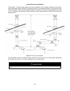
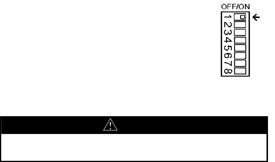
Dip switch number 1 is located in the top row of dip switches, 1 through 8 on the PC board. See the
following diagram to identify the correct switch. If you do not understand the information concerning the
dip switch settings or the location of the dip switch, contact Bradford White Sales (800-532-4020) or
Technical Service (800-334-3393) for assistance. Use the following examples and the previous
discussion on calculating the equivalent vent length to determine the correct setting for dip switch number
1.
Example #1:
You have 6 feet (1.82 m) of vent pipe and one 90 elbow.
D = 6 + (1 x 6) + (0 x 1.5)
D = 12 feet of equivalent vent pipe
Dip switch number 1 should be moved to OFF position.
Example #2:
You have 15 feet (4.57 m) of vent pipe and two 90 elbows.
D = 15 + (2 x 6) + (0 x 1.5)
D = 27 feet of equivalent vent pipe
Leave dip switch number 1 in the ON position (default setting).
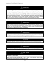
WARNING
Do not alter dip switch number 1 before using the formula and venting charts to determine the
equivalent vent length. All other dip switches with the exception of dip switch number 1, shown in
the illustration, MUST NOT be altered unless instructed to do so. Unauthorized adjustments can
cause property damage, personal injury, scalding, or death.
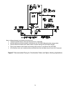
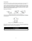
Figure 13. Dip Switch
Settings.