


SERVICE PROCEDURE RG-IX
ScreenLok
®
Flame Arrestor Cleaning
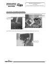
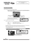
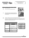
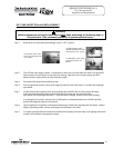
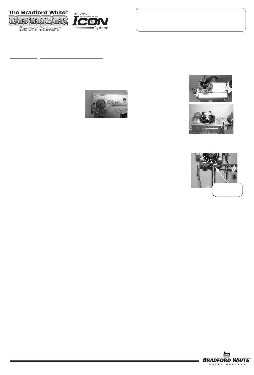
Step 1. Rotate knob of combination thermostat gas valve to the off position.
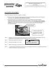
Step 2. Remove outer jacket door.
Step 3. Remove inner door per SERVICE PROCEDURE RG-I, step 3a through 3e.
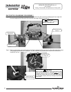
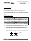
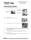
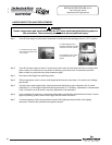
Step 4. Disconnect main burner feed line, pilot tube and thermocouple/thermopile
from combination thermostat gas valve and remove burner assembly
from combustion chamber.
NOTE: Feedline nut for natural gas control uses right hand threads,
LP control uses left hand thread.
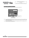
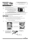
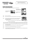
Step 5. Clean ScreenLok
®
Flame Arrestor using stiff brush, compressed air and/or shop vacuum to remove any scale or
other debris accumulation. Using a soft brush, clear jacket openings of any dirt, dust, restrictions or other obstructions.
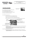
Step 6. Remove any debris from burner assembly per SERVICE PROCEDURE RG-V and reinstall burner assembly
into combustion chamber.
Step 7. Reconnect feedline, thermocouple and pilot tube to the combination thermostat/gas valve.
Step 8 Reinstall inner door per SERVICE PROCEDURE RG-I, steps 4 through 13.
Step 9. To resume operation follow the instructions located on the lighting instruction label or the lighting instruction
located in the installation and operation manual.
The Bradford White
DEFENDER
Safety System
®
ScreenLok
®
Flame Arrestor Cleaning
For White Rodgers Control,
depress knob slightly and rotate
clockwise to the “OFF” position.
For Robertshaw Control, rotate
knob clockwise to the “OFF”
position.
Feedline
Nut
For Honeywell Control, rotate
knob counter-clockwise to the
“OFF” position.
36
36
36