


SERVICE PROCEDURE RG-VI
Gas Control
Testing, Disassembly & Replacement (Honeywell)
The Bradford White
DEFENDER
Safety System
®
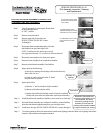
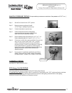
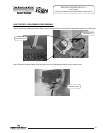
MANIFOLD PRESSURE TESTING (this procedure presumes a maximum line pressure of 14.0" w.c.)
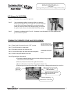
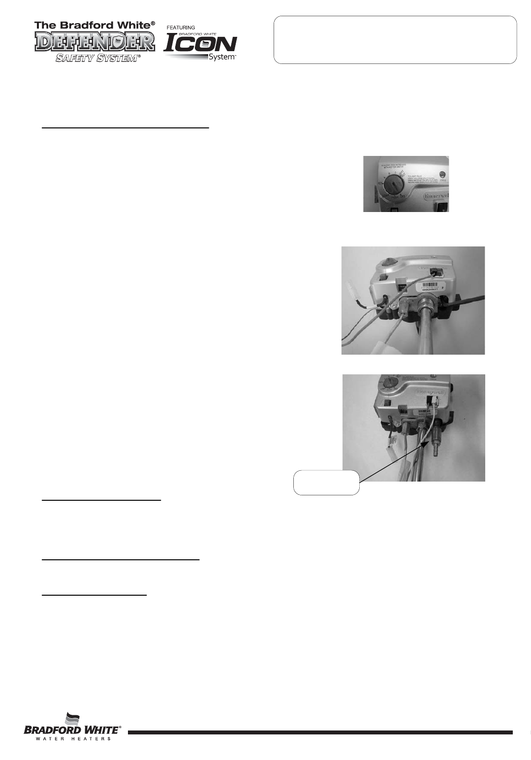
Step 1. Set the Gas Control to the “OFF” position.
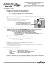
Step 2. Remove pressure tap plug and install
1/8" NPT pipe, coupling, & pressure tap.
Step 3. Connect manometer to pressure tap.
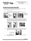
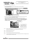
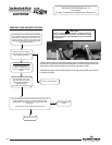
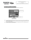
Step 4. Follow instructions located on the lighting
instructions label and proceed to light the main
burner and observe manometer reading.
Step 5. Proper operating range for natural gas is: 4.0" ±0.5" w.c.
Proper operating range for LP gas is: 10.0" ±0.5" w.c.
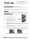
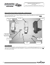
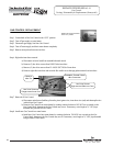
Step 6. If pressure is within the range specified in the previous
step, set Gas Control knob to the “OFF” position,
remove manometer and pressure tap, and replace
pressure tap plug. Check for gas leaks prior to placing
water heater back into operation by following the
instructions located on the lighting instruction label or the
lighting instructions located in the installation and
operation manual.
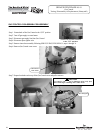
Step 7. If gas pressure is outside the specification noted above,
refer to “Honeywell Gas Control Testing, Disassembly,
and Replacement” to replace Gas Control or valve body.
THERMOPILE TESTING
See SERVICE PROCEDURE RG-II
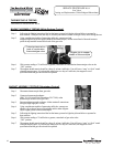
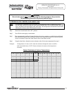
The Honeywell Gas Control is designed with an ECO device that will reset.
To reset the Gas Control after an error code (4), turn the Gas Control knob to the “OFF” position and wait a minimum
of (5) minutes before relighting following the instructions located on the lighting instruction label or the lighting
instructions located in the installation and operation manual.
ECO (Energy Cut Off) TESTING
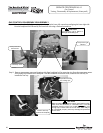
Gas Control shown in the “OFF” position
Pressure Tap
Shown Installed
21
21
21