


SERVICE PROCEDURE RG-VI
Gas Control
Testing, Disassembly & Replacement (Honeywell)
The Bradford White
DEFENDER
Safety System
®
GAS CONTROL REPLACEMENT
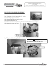
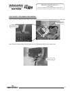
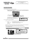
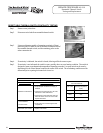
b) Reattach main burner feedline, pilot tube, piezo igniter wire, inner door wire (red) and thermopile wire
(white) to Gas Control. Attach inner door wire (red) to the positive (+) terminal and the thermopile wire
(white) to the negative (-) terminal.
Positive (+) Terminal
(red wire)
Negative (-) Terminal
(white wire)
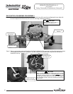
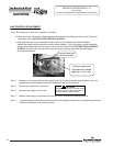
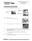
c) Gather piezo igniter wire, thermopile wire (white), inner door wire (red), and pilot tube and secure along
side of feedline using new wire tie provided.
d) Reconnect gas supply piping to inlet of Gas Control.
CAUTION
Use back up wrench on wrench boss
of Gas Control, never use back up
wrench on body of Gas Control.
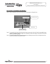
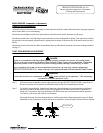
Step 9. Reinstallation of inner door assembly.
a) Prior to reinstallation of inner door, fully inspect inner door gasket for the following:
> Tears > Gasket Adhesion to inner door
> Missing Material > Other imperfections that will inhibit proper seal
> Cracks > Material left on combustion chamber
> Dirt or debris
If the gasket is not effected by any of the above, gasket replacement will not be required. If replacement is
required, replace using new gasket kit following the instructions provided with kit.
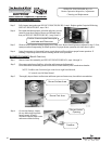
b) Clean any gasket residue or other debris from combustion chamber surface before installing
the inner door/gasket assembly.
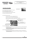
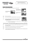
c) Position thermopile wire, pilot tube and Piezo wire against left side inner door flange gasket. DO NOT ROUTE
THROUGH RADIUSED CHANNEL WITH FEEDLINE. Be sure that thermopile and pilot tube are not
in position to interfere with outer jacket burner access door when reinstalled.
Position thermopile, pilot
tube and Piezo wire.
WARNING
A seal breach may result in a fire or
explosion causing property damage,
personal injury or death.
Step 8. Install new Gas Control into water heater (contintued).
29
29
29