


SERVICE PROCEDURE RG-VI
Gas Control
Testing, Disassembly & Replacement (Honeywell)
The Bradford White
DEFENDER
Safety System
®
GAS CONTROL REPLACEMENT
Step 9. Reinstallation of inner door assembly (continued).
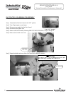
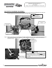
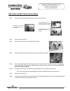
d) Firmly place right side inner door flange against the left side inner door flange and secure with (2) hex drive
screws from step 6c. DO NOT OVER TIGHTEN SCREWS.
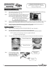
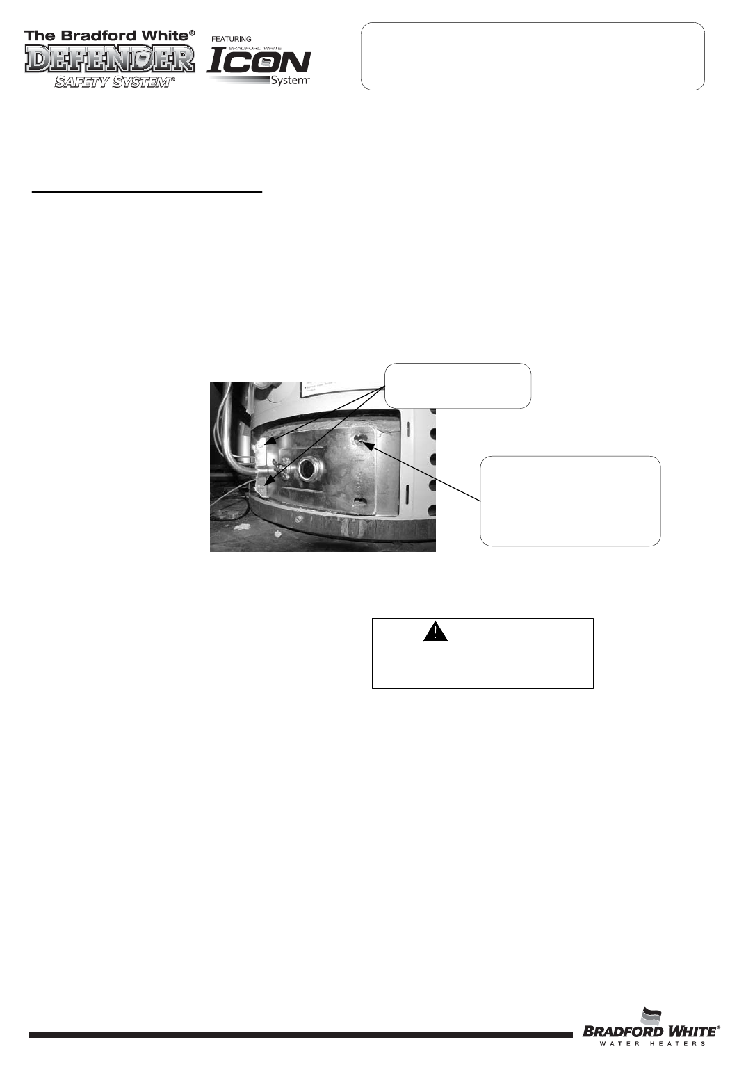
e) Align right side inner door to combustion chamber and verify the fastener holes of the combustion
chamber are aligned with the right side inner door slotted openings. Verify seal integrity around combustion
opening. Secure right side inner door using (2) hex drive screws from step 6b. DO NOT OVER TIGHTEN
SCREWS. Verify both left and right sides of the inner door are properly positioned and sealed against
the combustion chamber.
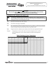
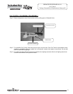
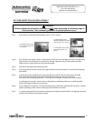
Step 10. Reconnect (2) red wire leads from pilot assembly and Gas Control to resettable thermal switch. Note: wire
terminations are interchangeable with either resettable thermal switch connection.
Step 11. Replace outer jacket burner access door.
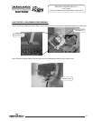
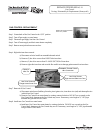
Step 12. Reconnect gas supply to Gas Control.
Step 13. Resume water supply to water heater. Be sure tank is full of water before resuming operation.
Step 14. To resume operation follow the instructions located on the lighting instruction label or the lighting instructions
located in the installation and operation manual.
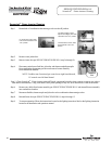
Verify threaded hole
alignment with slotted
openings in inner door.
Secure flange with
hex drive screws.
30
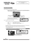
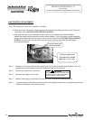
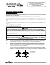
CAUTION
Use back up wrench on wrench boss
of Gas Control, never use back up
wrench on body of Gas Control.
30
30