


SERVICE PROCEDURE RG-VI
Gas Control
Testing, Disassembly & Replacement (Honeywell)
The Bradford White
DEFENDER
Safety System
®
TEMPERATURE SENSOR TESTING
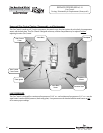
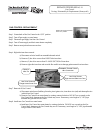
Temperature Sensor Testing
Following “Gas Control
Disassembly/Reassembly”
instructions, disassemble Gas
Control to access temperature
sensor.
N
Y
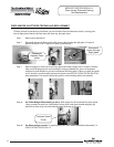
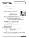
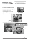
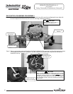
Using a multi-meter set to the ohms setting, insert one meter probe (see caution)
into center wire position of thermal well connector, insert the second probe (see
caution) into either of the outside wire positions (see photo on left).
Alternate the probe on the outside position to the opposite outside wire position
(see photo on right).
Replace temperature
sensor
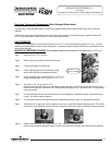
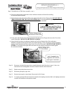
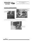
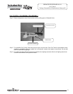
With the temperature sensor still
in the back plate, use a multi-
meter set to the Ohms setting,
determine the resistance of
temperature sensor
(see caution and photos above)
Replace Gas Control
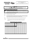
Once the temperature sensor resistance values are known, the
water temperature must also be known to determine if the
resistance values are correct. See next page to obtain water
temperature.
Are temperature sensor resistance values correct?
CAUTION
DO NOT use standard multimeter probes for this test.
Doing so will damage connector. Use special pin type
electronic probes or small diameter wire pins inserted
into connector.
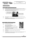
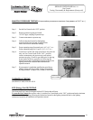
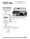
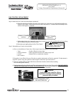
If Control has gone into lockout due to excessive
tank temperature (four flash, three second pause)
reset control by rotating gas control knob to “OFF”
position and wait a minimum of (5) minutes. Then
follow lighting instructions and return gas control
knob to desired setpoint.
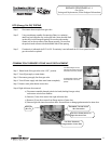
Observe Green LED indicator.
Does error code 4 (four flash, three
second pause) continue?
Resume normal operation.
Y
N
22
22
22