


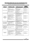

The following test should be performed while the pilot flame is on.
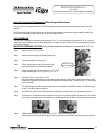
Step 1. Turn knob to pilot position and depress.
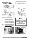
Step 2. Continue pressing knob and remove red (+) wire from resettable thermal door switch.
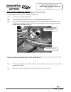
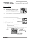
Step 3. Using a multimeter capable of measuring millivolts, connect the positive side of the multimeter to the
terminal of the resettable thermal door switch. Connect the negative side of the multimeter to any earth
ground location (jacket base, screw, etc.).
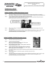
OPEN CIRCUIT THERMOPILE TESTING (Honeywell Gas Control)
Normal thermopile operation will be between 350mV - 850mV. If reading is less than 350mV, replacement of pilot
assembly is recommended following SERVICE PROCEDURE RG-III.
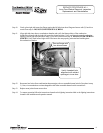
Step 4. If thermopile reading is between 350mV - 850mV, remove multimeter and reconnect red wire to positive (+)
terminal of Gas Control.
Step 5. Release Gas Control knob and turn to desired setting to resume normal operation.
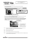
SERVICE PROCEDURE RG-II
Thermocouple/Thermopile Testing and
Replacement
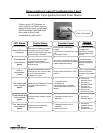
Resettable Thermal Door
Switch Terminal (+)
Jacket Base Screw (-)
12
12
12