


7
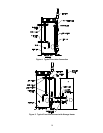
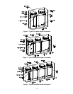
LATCHES – The latches allow easy access for servicing the water heater from the top. Simply remove the two latches
for servicing and re-latch upon completion. No tools are required to obtain access to the top of the water heater.
MIXING VALVE – This water heater is supplied with an ASSE approved mixing valve to reduce the potential for scald
injury when thermostat settings over 120˚F (49ºC) are used for dishwashers or other appliances. The mixing valve
reduces the discharge temperature by mixing cold and hot water in the branch supply lines. Refer to the instructions
supplied with the mixing valve for installation procedures and device specifications. The mixing valve is located inside
the control compartment.
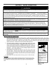
SCALDING WARNING
ASSE APPROVED MIXING DEVICE MUST BE INSTALLED
TO PROVIDE PROTECTION FROM SCALDING
This water heater can deliver scalding temperature water at any faucet in the system if installed without installing
the supplied ASSE mixing device. By setting the thermostat on this water heater to obtain an increased water
temperature without properly installing the supplied mixing device, you may create the potential for scald injury.
To protect against injury, the supplied ASSE approved mixing device (a device to limit the temperature of water
to protect against scald injury via mixing hot and cold water supply) must be properly installed in the water
system. This valve will reduce point of discharge temperature in branch supply lines.
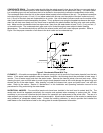
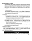
TEMPERATURE AND PRESSURE RELIEF VALVE –
WARNING
Keep clear of the combination temperature and pressure relief valve discharge line outlet. The
discharge may be hot enough to cause scald injury. The water is under pressure and may splash.
For protection against excessive temperatures and pressure, install temperature and pressure
protective equipment required by local codes, but not less than a combination temperature and
pressure relief valve certified by a nationally recognized testing laboratory that maintains periodic
inspection of production of listed equipment or materials as meeting the requirements of the Standard
for Relief Valves and Automatic Gas Shutoff Devices for Hot Water Supply Systems, ANSI Z21.22 and
the Standard CAN1-4.4 Temperature, Pressure, Temperature and Pressure Relief Valves and Vacuum
Relief Valves. The combination temperature and pressure relief valve must be marked with a maximum
set pressure not to exceed the maximum working pressure of the water heater. The combination
temperature and pressure relief valve rating must not be less than the hourly rating of the water heater
Install the combination temperature and pressure relief valve into the opening provided and marked for
this purpose on the water heater.
Note: Some models may already be equipped or supplied with an installed combination temperature
and pressure relief valve. Verify that the combination temperature and pressure relief valve complies
with local codes. If the combination temperature and pressure relief valve does not comply with local
codes, replace it with one that does. Follow the installation instructions above on this page.
Install a discharge line so that water discharged from the combination temperature and pressure relief
valve will exit within 6 inches (15.3 cm) above, or any distance below the structural floor and cannot
contact any live electrical part. The discharge line is to be installed to allow for complete drainage of
both the combination temperature and pressure relief valve and the discharge line. The discharge
opening must not be subjected to blockage or freezing. DO NOT thread, plug or cap the discharge line.
It is recommended that a minimum clearance of 4 inches (10.2 cm) be provided on the side of the water
heater for servicing and maintenance of the combination temperature and pressure relief valve.
Do not place a valve between the combination temperature and pressure relief valve and the tank!