


24
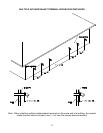
The vent system must terminate so that proper clearances are maintained as cited in local codes or the latest
edition of the National Fuel Gas Code, ANSI Z223.1.73.4e and 7.8a, b as follows:
1. Do not terminate near soffit vents or crawl space or other area where condensate or vapor could create a
nuisance or hazard or cause property damage.
2. Do not terminate the exhaust vent terminal where condensate or vapor could cause damage or could be
detrimental to the operation of regulators, relief valves, or other equipment.
3. Do not terminate the exhaust vent terminal over public area or walkways where condensate or vapor can
cause nuisance or hazard.
4. The vent must terminate a minimum of 12 inches (30.5 cm) above expected snowfall level to prevent
blockage of the vent termination.
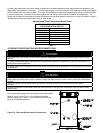
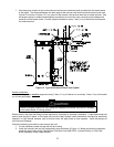
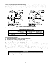
5. The manufacturer requires the centerline distances between the air intake and exhaust vent terminals to
be a minimum of 36 inches (91.4 cm) apart and the exhaust terminal must extend 6 inches (15.3 cm)
past the air intake terminal.
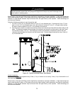
Vent pipes serving power vented appliances are classified by building codes as “vent connectors”. Required
clearances from combustible materials must be provided in accordance with information in this manual under
LOCATION OF WATER HEATER and CLEARANCES, and with National Fuel Gas Code and local codes.
All vent pipes and terminals are to have a 1” minimum clearance to combustibles. DO NOT use the placement of
insulation or other materials in the required clearance spaces surrounding the venting to combustible material
unless otherwise specified.
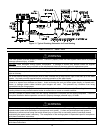
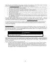
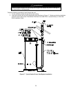
Horizontal Installation:
In a horizontal application, it is important that condensate not be allowed to buildup in the exhaust vent pipe. To
prevent this from happening, the pipe should be installed with a slight upward slope so the condensate will run
back toward the water heater. The vent system must be supported every 5 feet (1.5 m) of vertical run and every 3
feet (.9 m) of horizontal run of vent pipe length.
CAUTION
Failure to properly support the vent piping with hangers and clamps may result in damage to
the water heater or venting system.
Stress levels in the pipe and fittings can be significantly increased by improper installation. If rigid pipe clamps are
used to hold the pipe in place, or if the pipe cannot move freely through a wall penetration, the pipe may be directly
stressed, or high thermal stresses may be formed when the pipe heats up and expands. Install accordingly to
minimize such stresses.
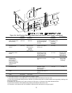
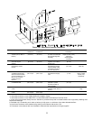
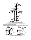
Follow the following procedure to vent through the wall:
1. Cut two 2 ½ inch (6.4 cm) diameter holes for 2 inch (5.1 cm) diameter pipe, in the wall with the centerline
hole distances at least 36 inches (91.4 cm) apart in the location where the exhaust vent and air intake
terminals will exit the outside wall if vented on the same wall. If venting with 3 inch (7.6 cm) pipe or 4 inch
(10.2 cm) diameter pipe, use a bell reducer to reduce to 2 inch (5.1 cm) pipe before exiting the wall to use
the supplied 2 inch (5.1 cm) diameter vent terminals.