


25
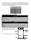
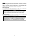
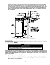
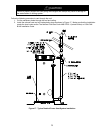
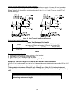
2. Use the proper cement to secure the exhaust vent and air intake terminals provided with the water heater
to the pipes. The distance between the back edge of the exhaust vent terminal and the exterior wall (see
Figure 13) must be 6 inches (15.3 cm) more for the exhaust vent terminal than the air intake terminal. Use
the proper cement or sealant and assembly procedures to secure the vent connector joints between the
terminal and the blower outlet. Provide support brackets for every 3 feet (.9 m) of horizontal vent beyond
the intake terminal.
Figure 13. Typical Horizontal Direct Vent System
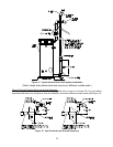
Vertical Installation:
Vertical venting system must be supported every 5 feet (1.5 m) of vertical run and every 3 feet (.9 m) of horizontal
run of vent pipe length.
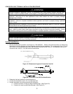
CAUTION
Failure to properly support the vent piping with hangers and clamps may result in damage
to the water heater or venting system.
Stress levels in the pipe and fittings can be significantly increased by improper installation. If rigid pipe clamps are
used to hold the pipe in place, or if the pipe cannot move freely through a wall penetration, the pipe may be directly
stressed, or high thermal stresses may be formed when the pipe heats up and expands. Install accordingly to
minimize such stresses.
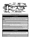
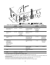
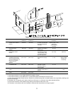
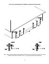
Follow the following procedure to vent through the roof:
1. Cut the necessary holes through the roof and ceiling.
2. Install the exhaust vent and air intake plastic pipes as shown in Figure 14. Make sure that the installation
meets the local codes and/or The National Fuel Gas Code ANSI Z223.1 (Latest Edition) or CGA/CAN
B149 Installation Code (Latest Edition).