


36
INITIAL PREPARATION
1. Make sure the solvent cement you are planning to use is designed for the specific application you are
attempting.
2. Know the physical and chemical characteristics and limitations of the PVC, PVC cellular core, ABS or CPVC
piping materials that you are about to use.
3. Know the reputation of your pipe and cement manufacturer and their products.
4. Know your own qualifications or those of your contractor. The solvent welding technique of joining PVC, PVC
cellular core, ABS or CPVC pipe is a specialized skill just as any other pipe fitting technique.
5. Closely supervise the installation and inspect the finished job before start-up.
6. Contact the manufacturer, supplier, or competent consulting agency if you have any questions about the
application or installation of PVC, PVC cellular core, ABS or CPVC pipe.
7. Take the time and effort to do a professional job. Shortcuts will only cause you problems and delays in start-
up. The majority of failures in these systems are the result of shortcuts and/or improper joining techniques.
SAFETY PRECAUTION: PRIMERS AND CEMENTS ARE EXTREMELY FLAMMABLE AND MUST NOT BE STORED
OR USED NEAR HEAT OR OPEN FLAME. ALSO, USE ONLY IN A WELL VENTILATED AREA.
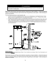
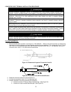
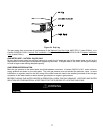
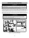
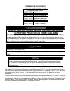
SECTION VII: GAS CONNECTIONS
WARNING
Connect this water heater only to the type of gas as shown on the rating plate. Use clean black iron pipe or
equivalent material approved by local codes and ordinances. (Dirt and scale from the pipe can enter the gas valve
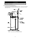
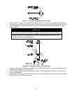
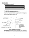
and cause it to malfunction). The inlet gas line must have at least a 3 inch (7.62 cm) drip leg (sediment trap)
installed as close to the water heater’s gas valve as possible. A ground joint union must be installed in the gas
supply line, as close to the water heater as possible, to permit servicing of the water heater. Compounds used on
the threaded joints of the gas piping must be resistant to the action of liquefied petroleum gases/propane gas. DO
NOT apply pipe dope to the gas valve inlet and make certain that no pipe dope has become lodged in the inlet
screen of the gas valve. Extreme care must be taken to ensure no pipe dope enters the gas valve and to avoid
excessive torque when tightening the gas supply line to the gas valve. Excessive torque may result in cracking of
the gas valve housing. The suggested maximum torque is 31.5 foot lbs. (4.4 kg-m). The manufacturer of this
water heater will not be liable for any damage or injury caused as a result of a cracked gas inlet as a result of
excessive torque.
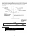
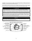
This water heater and its gas connection must be leak tested before placing the water heater in operation. Check
for gas leaks with a soap and water solution and a brush or a commercial leak detector fluid.
NEVER USE A MATCH OR OPEN FLAME FOR TESTING!
The water heater is not intended for operation at higher than 14 inches (3483.8 Pa) water column (½ psi (3.5 kPa))
supply gas pressure. Higher gas supply pressures require supplemental reducing service regulation. Exposure to
higher gas supply pressure may cause damage to the gas controls, which could result in a fire or explosion. If
overpressure has occurred such as through improper testing of gas lines or emergency malfunction of the supply
system, the gas valve must be checked for safe operation. Make sure that the outside vents on the supply
regulators and the safety vent valves are protected against blockage. These are parts of the gas supply system,
not the water heater.
CAUTION
The water heater and individual shutoff valve must be disconnected from the gas supply piping system during any
pressure testing of the system at test pressures in excess of ½ psi (3.5 kPa). The water heater must be isolated
from the gas supply piping system by closing its manual shutoff valve during any pressure testing of the gas supply
system at test pressures equal to or less than ½ psi (3.5 kPa). The supply line must be capped when not
connected to the water heater.
If copper supply lines are used, they must be internally tinned and certified for gas service.