


34
Horizontal Installation:
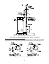
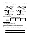
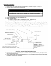
1. Become familiar with coaxial vent kit part no. 239-44069-02 as shown in Figures 19 through 21.
2. Determine the best location for the termination kit.
NOTICE
Position termination where vent vapors will not be adversely affected by wind condition.
Position termination where it will not be damaged or be subjected to foreign objects.
Position termination where vapors will not be objectionable.
3. Cut the recommended 4 inch (10.2 cm) diameter hole.
4. Partially assemble vent kit.
a. Cement Y concentric fitting to larger diameter kit pipe. (See Figure 20).
b. Cement rain cap to smaller diameter kit pipe. (See Figure 21).
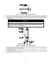
5. Install concentric Y fitting and pipe assembly through the structure’s hole and field-supplied roof boot/flashing.
Do not allow insulation or other materials to accumulate inside pipe assembly when installing through the hole.
6. Install rain cap and small diameter pipe assembly in concentric Y fitting and large pipe assembly. Ensure small
diameter pipe is cemented and bottomed in concentric Y fitting.
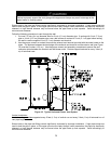
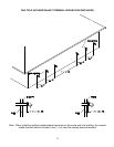
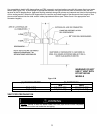
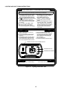
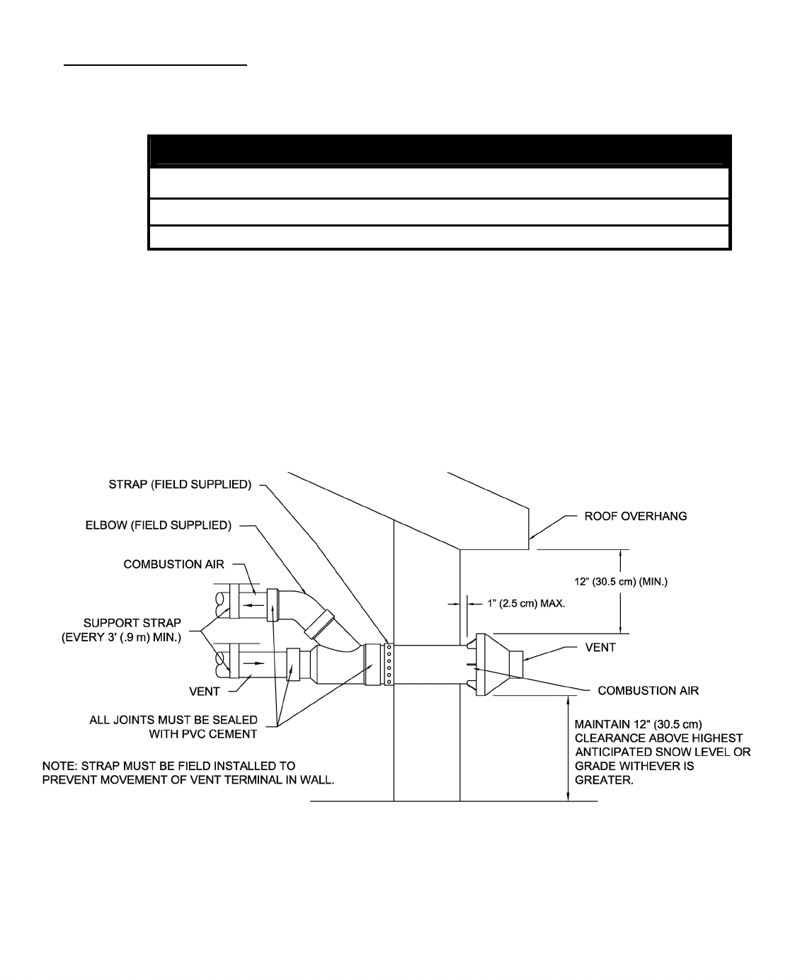
7. Secure assembly to structure as shown in Figure 23A. Ensure clearances as shown in Figure 23A.
Figure 23A. Concentric Vent Side Wall Attachment
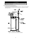
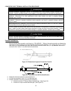
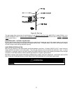
8. Cement heater combustion-air and vent pipes to concentric Y fitting termination assembly. See Figure 23A &
23B for proper pipe attachment.
9. Operate heater through one cycle to ensure combustion-air and vent pipes are properly connected and sealed
to concentric vent termination connections.