


37
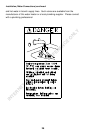
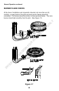
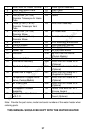
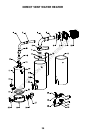
1. Direct Vent-Air Intake Terminal 21. Piezo Ignitor Assembly
2. Outer Wall Mount Plate 22. Drain Valve
3. Backing Plate 23. Outer Door
4. Five (5) inch (12.7 cm)
Diameter Telescopic Air Intake
Tube
24. Jacket
5. Three (3) inch (7.6 cm)
Diameter Telescopic Vent
Tube
25. Inner Door Assembly
6. Five (5) inch (12.7 cm)
Diameter Elbow
26. Air Intake Boot
7. Three (3) inch (7.6 cm)
Diameter Elbow
27. Air Intake Boot Gasket
8. Plenum 28. Pilot Assembly w/Electrode
9. Plenum Gasket 29. Gas Feed Line (Burner)
10. Flue Reducer 30. Main Burner Orifice
11. Jacket Top 31A. 42 Port Steel Burner
12. Insulation 31B. 65 Port Cast Iron Burner
(Certain Models)
13. Glass Lined Tank 32. Radiation Shield
14. Flue Baffle Assembly 33A. Direct Vent-Air Intake Kit A
(Optional)
15. Dip Tube & Nipple 33B. Direct Vent-Air Intake Kit B
(Optional)
16. Anode Rod & Nipple 33C. Direct Vent-Air Intake Kit C
(Supplied & Optional)
17. Temperature-Pressure Relief
Valve (Certain Models)
33D. Direct Vent-Air Intake Kit D
(Optional)
18. Air Intake Tube 33E. Direct Vent-Air Intake Kit E
(Optional)
19. Combustion Chamber
Assembly
34. Loctite Ultra Blue 587 RTV
Silicone Sealant
20. Combination Gas Control
w/E.C.O.
35. Direct Vent-Air Intake Terminal
Guard (Optional)
Note: Provide the part name, model and serial numbers of the water heater when
ordering parts.
THIS MANUAL SHOULD BE KEPT WITH THE WATER HEATER
INTERNET VERSION FOR REFERENCE ONLY