


26
WARNING
For protection against excessive temperatures and pressure, install
temperature and pressure protective equipment required by local codes,
but not less than a combination temperature and pressure relief valve
certified by a nationally recognized testing laboratory that maintains
periodic inspection of production of listed equipment or materials as
meeting the requirements of the Standard for Relief Valves and Automatic
Gas Shutoff Devices for Hot Water Supply Systems, ANSI Z21.22 and the
Standard CAN1-4.4 Temperature, Pressure, Temperature and Pressure
Relief Valves and Vacuum Relief Valves. The combination temperature
and pressure relief valve shall be marked with a maximum set pressure not
to exceed the maximum working pressure of the water heater. The hourly
BTU discharge capacity or the rated steam relief capacity of the
combination temperature and pressure relief valve shall not be less than
the input rating of the water heater.
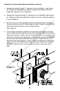
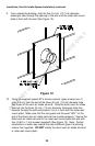
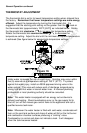
Install the combination temperature and pressure relief valve into the
opening provided and marked for this purpose on the water heater.
Note: Some models may already be equipped or supplied with a
combination temperature and pressure relief valve. Verify that the
combination temperature and pressure relief valve complies with local
codes. If the combination temperature and pressure relief valve does not
comply with local codes, replace it with one that does. Follow the
installation instructions above on this page.
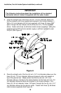
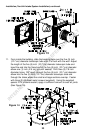
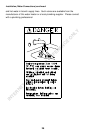
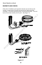
Install a discharge line which terminates six (6) inches (15 cm) above the
floor, or any distance below the structural floor, to the outlet of the
combination temperature and pressure relief valve. DO NOT allow water
from the discharge line to contact any live electrical part. The discharge
line is to be installed to allow for complete drainage of both the
combination temperature and pressure relief valve and the discharge line.
The water from the discharge line must be directed to a suitable drain or
area that will not be damaged by water (Refer to page 6 “LOCATING THE
WATER HEATER.” The discharge opening must not be subjected to
blockage or freezing. DO NOT thread, plug or cap the discharge line.
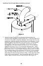
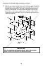
It is recommended that a minimum clearance of four (4) inches (10.2 cm)
be provided on the side of the water heater for servicing and maintenance
of the combination temperature and pressure relief valve.
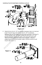
Do not place a shutoff valve between the combination temperature and
pressure relief valve and the water heater, or on discharge pipes between
such valves or the atmosphere.
INTERNET VERSION FOR REFERENCE ONLY