


17
Installation continued-
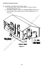
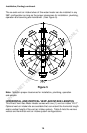
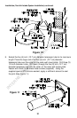
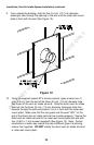
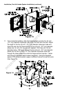
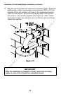
VENT-AIR INTAKE SYSTEM INSTALLATION
WARNING
The vent-air intake system must be properly installed. Failure to
properly install the vent-air intake system could result in property
damage, personal injury or death.
Do not install any damaged vent-air intake system components.
Contact the manufacturer of the water heater for replacement parts.
Tools Required For Vent-Air Intake Installation
The following minimum tools are required to properly install the vent-
air intake system. Note: Wall construction will determine tool usage.
Tape Measure
Drill
3/16 inch Diameter Drill Bit(s)
1/8 inch Diameter Drill Bit(s)
Masonry Drill Bit(s) (For Poured Concrete, Concrete Block and Brick Wall
Construction)
Reciprocating Saw w/appropriate Blade(s) (Dependent on Wall
Construction)
Chisel (For Poured Concrete, Concrete Block and Brick Wall Construction)
Hammer (For Poured Concrete, Concrete Block and Brick Wall
Construction)
1/4 & 5/16 inch Nut Drivers (Preferred) or Slotted Head Screwdriver
Phillips Head Screwdriver
IMPORTANT
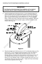
When the following instructions specify, to seal a vent-air intake joint,
use only Loctite Ultra Blue 587 RTV Silicone sealant. A tube of Loctite
Ultra Blue 587 RTV Silicone sealant is supplied with every direct vent
water heater and each optional vent-air intake kit. Make sure that all
joints are completely sealed.
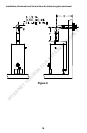
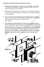
When drilling pilot holes for the #8 sheet metal screws through the
five (5) inch (12.7 cm) diameter components, be careful not to drill into
the inner three (3) inch (7.6 cm) diameter components.
INTERNET VERSION FOR REFERENCE ONLY