


19
Installation (Vent-Air Intake System Installation) continued-
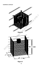
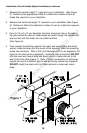
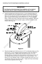
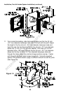
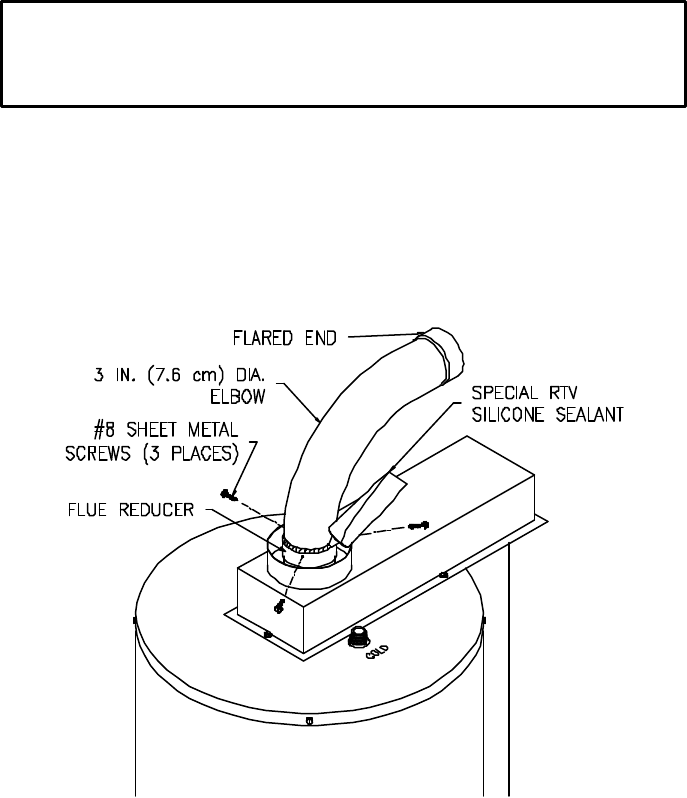
5. Insert the straight end of the three (3) inch (7.6 cm) diameter elbow into
the flue reducer until firmly seated and oriented in the correct direction.
With a 1/8 inch diameter drill bit (not supplied), drill three (3) holes, 120
o
apart, through the flue reducer into the three (3) inch (7.6 cm) diameter
elbow. Fasten with three (3) #8 sheet metal screws (supplied). Using the
supplied special RTV silicone sealant, apply a sufficient amount to seal
the joint (See Figure 8).
Figure 8
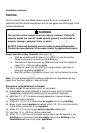
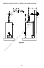
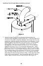
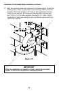
6. Place the straight end of the five (5) inch (12.7 cm) diameter elbow over the
three (3) inch (7.6 cm) diameter elbow and plenum collar until seated on
top of the plenum box. Make certain that the five (5) inch (12.7 cm)
diameter elbow is oriented in the same direction as the three (3) inch (7.6
cm) diameter elbow and both are oriented in the correct direction. Drill
three (3) 1/8 inch diameter holes, 120
o
apart, through the five (5) inch (12.7
cm) diameter elbow into the plenum collar. Fasten with three (3) #8 sheet
metal screws (supplied) (See Figure 9).
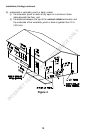
IMPORTANT
The following instructions detail the installation of the standard
horizontal vent-air intake kit supplied with the water heater.
INTERNET VERSION FOR REFERENCE ONLY