


20
Installation (Vent-Air Intake System Installation) continued-
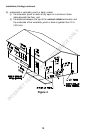
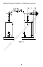
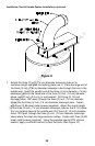
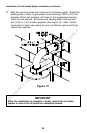
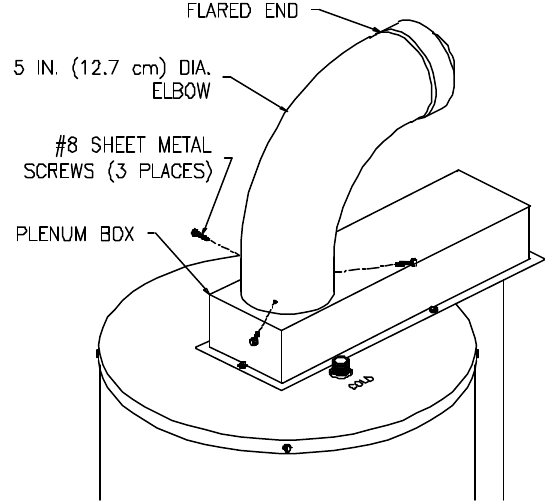
Figure 9
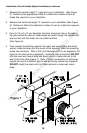
7. Extend the three (3) inch (7.6 cm) diameter telescopic tube to its
maximum length and slide the backing plate over it. Place the large end of
the three (3) inch (7.6 cm) diameter telescopic tube through the hole in the
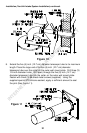
outside wall. Insert the smaller end of the three (3) inch diameter (7.6 cm)
telescopic tube into the flared end of the three (3) inch (7.6 cm) diameter
elbow, one (1) inch (2.5 cm) (or until seated). Drill three (3) 1/8 inch
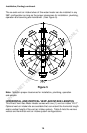
diameter holes, 120
o
apart, through the three (3) inch (7.6 cm) diameter
elbow into the three (3) inch (7.6 cm) diameter telescopic tube. Fasten
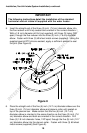
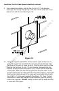
with three (3) #8 sheet metal screws (supplied). Adjust the overall length
of the three (3) inch (7.6 cm) diameter telescopic tube so that 2-1/2 inches
(6.4 cm) extends beyond the outside wall. Drill three (3) 1/8 inch diameter
holes, 120
o
apart, through the three (3) inch (7.6 cm) diameter telescopic
tubes where the small and large sections overlap. Fasten with three (3) #8
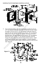
sheet metal screws (supplied). Using the supplied special RTV silicone
sealant, apply a sufficient amount to seal the joints (See Figure 10).
INTERNET VERSION FOR REFERENCE ONLY