


18
Installation (Vent-Air Intake System Installation) continued-
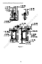
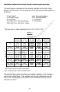
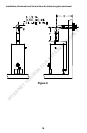
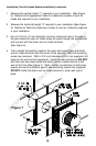
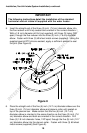
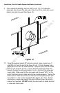
1. Measure the vertical height “Y” required in your installation. (See Figure
6). Reference the appropriate Table A to determine number of vent-air
intake kits required in your installation.
2. Measure the horizontal length “X” required in your installation (See Figure
6). Reference Table A to determine number of vent-air intake kits required
in your installation.
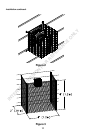
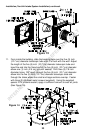
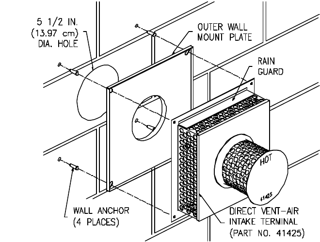
3. Cut a 5-1/2 inch (14 cm) diameter minimum clearance hole in the wall at
the point where the vent-air intake tubes will pass through the outside wall
and connect with the direct vent-air intake terminal
(See Figure 6).
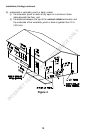
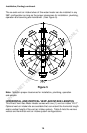
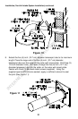
4. From outside the building, position the outer wall mount plate and direct
vent-air intake terminal over the center of the opening. Mark the mounting
screw hole locations. With a 3/16 inch diameter drill bit (not supplied), drill
holes for the wall anchors (supplied). Install the wall anchors but DO NOT
affix the outer wall mount plate and direct vent-air intake terminal to the
wall at this time (See Figure 7). Note: Certain construction of walls may
require the use of a different type of wall anchoring means than supplied.
DO NOT modify the direct vent-air intake terminal or outer wall mount
plate.
Figure 7
INTERNET VERSION FOR REFERENCE ONLY