


Page 9
Brute Deluxe (500-2000)
lation Instructions. Horizontal portions of the venting
system must be supported to prevent sagging and may
not have any low sections that could trap condensate.
The unit must not support the weight of the vent pipe.
Horizontal runs must slope downwards not less than ¼
inch per foot (2 cm/m) from the unit to the vent terminal.
Reference Table 1 for the size of the Category III vent
system. Up to three elbows can be used with 50 linear
feet (15.2m) of pipe. Subtract 10 allowable linear feet
(3.0m) for every additional elbow used.
WARNING
The outdoor vent terminal gets hot. Unit must be
installed in such a way as to reduce the risk of burns
from contact with the vent terminal.
2.3 Locating Vent & Combustion Air
Terminals
2.3.1 Side Wall Vent Terminal
The appropriate side wall vent hood must be used,
and is listed in the installation and operation manual.
The terminal provides a means of installing the vent
piping through the building wall, and must be located in
accordance with ANSI Z223.1/NFPA 54 and applicable
local codes. In Canada, the installation must be in
accordance with CSA B149.1 or .2 and local applicable
codes. Consider the following when installing the
terminal:
1. Figure 4 shows the requirements for mechanical
vent terminal clearances for the U.S. and Canada.
2. Vent terminals for condensing appliances or
appliances with condensing vents are not permitted
to terminate above a public walkway, or over an
area where condensate or vapor could create a
nuisance or hazard.
3. Locate the vent terminal so that vent gases cannot
be drawn into air conditioning system inlets.
4. Locate the vent terminal so that vent gases cannot
enter the building through doors, windows, gravity
inlets or other openings. When possible, locations
under windows or near doors should be avoided.
5. Locate the vent terminal so that it cannot be
blocked by snow. The National Fuel gas code
requires that it be at a minimum of 12" above
grade. In a location that has the possibility of snow
accumulation, it is critical the installer places the
vent at least 12" higher than the maximum potential
snow line. Seek local municipalities and their
codes for appropriate installation techniques.
6. Locate the terminal so the vent exhaust does not settle
on building surfaces or other nearby objects. Vent
products may damage such surfaces or objects.
7. If the boiler or water heater uses ducted
combustion air from an intake terminal located on
the same wall, locate the vent terminal at least 3
feet (0.9m) horizontally from the combustion air
terminal, and locate the vent terminal at least 1 foot
(0.3m) above the combustion air terminal.
2.3.2 Side Wall Combustion Air Terminal
The side wall combustion air terminal (see Table
2) must be used when the unit takes its combustion air
through a duct from a side wall. Consider the following
when installing the terminal:
1. Do not locate the air inlet terminal near a source of
corrosive chemical fumes (e.g., cleaning fluid,
chlorinated compounds, etc.)
2. Locate the terminal so that it will not be subject to
damage by accident or vandalism.
3. Locate the combustion air terminal so that it cannot
be blocked by snow. The National Fuel gas code
requires that it be at a minimum of 12" above
grade. Depending on local conditions, the installer
should ensure that it remains at least 12" above the
maximum potential snow line. Seek local
municipalities and their codes for appropriate
installation techniques.
WARNING: It is critical that the combustion air
intake and the vent terminals remain at least 12"
above the maximum potential snow line. If either
the vent terminal or the air terminal is blocked by
snow, there may be potential for the unit to
produce excess carbon monoxide and or
recirculate flue gasses into the building/dwelling.
Personal injury or DEATH may occur. Natural
snowfall, drifting, and banking should all be taken
into account when locating the terminals in a
potential snow environment.
4. If the Brute Deluxe is side-wall vented to the same
wall, locate the vent terminal at least 3 feet (0.9m)
horizontally from the combustion air terminal, and
locate the vent terminal at least 1 foot (0.3m) above
the combustion air terminal (see Figure 4).
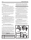
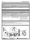
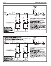
2.3.3 Vertical Vent Terminal
When the unit is vented through the roof, the vent
must extend at least 3 feet (0.9m) above the point at
which it penetrates the roof. It must extend at least 2 feet
(0.6m) higher than any portion of a building within a
horizontal distance of 10 feet (3.0m), and high enough
above the roof line to prevent blockage from snow.
When the combustion air is taken from the roof, the
combustion air must terminate at least 12" (30cm) below
the vent terminal (see Figure 3). Seek local
municipalities and their codes for appropriate
installation techniques.
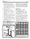
TERM DESCRIPTION
Pipe Must comply with UL Standard 1738
such as Type 29-4C Stainless Steel
(either insulated or non-insulated).
Joint Follow vent manufacturer’s instructions
Sealing
Table 5. Required Horizontal Venting Material.