


Page 11
Brute Deluxe (500-2000)
From Massachusetts Rules and Regulations 248 CMR 5.08:
(a) For all side wall horizontally vented gas fueled equipment
installed in every dwelling, building or structure used in
whole or inpart for residential purposes, including those
owned or operated by the Commonwealth and where the
side wall exhaust vent termination is less than seven (7)
feet above finished grade in the area of the venting,
including but not limited to decks and porches, the
following requirements shall be satisfied:
1.
INSTALLATION OF CARBON MONOXIDE DETECTORS.
At the time of installation of the side wall horizontal vented gas
fueled equipment, the installing plumber or gasfitter shall
observe that a hard-wired carbon monoxide detector with an
alarm and battery back-up is installed on the floor level where
the gas equipment is to be installed. In addition, the installing
plumber or gasfitter shall observe that a battery operated or
hard-wired carbon monoxide detector with an alarm is installed
on each additional level of the dwelling, building or structure
served by the side wall horizontal vented gas fueled equipment.
It shall be the responsibility of the property owner to secure the
services of qualified licensed professionals for the installation
of hard-wired carbon monoxide detectors.
a. In the event that the side wall horizontally vented gas fueled
equipment is installed in a crawl space or an attic, the hard-
wired carbon monoxide detector with alarm and battery back-
up may be installed on the next adjacent floor level.
b. In the event that the requirements of this subdivision cannot
be met at the time of completion of installation, the owner shall
have a period of thirty (30) days to comply with the above
requirements; provided, however, that during said thirty (30)
day period, a battery operated carbon monoxide detector with
an alarm shall be installed.
2.
APPROVED CARBON MONOXIDE DETECTORS. Each
carbon monoxide detector as required in accordance with the
above provisions shall comply with NFPA 720 and be ANSI/UL
2034 listed and IAS certified.
3.
SIGNAGE. A metal or plastic identification plate shall be
permanently mounted to the exterior of the building at a
minimum height of eight (8) feet above grade directly in line
with the exhaust vent terminal for the horizontally vented gas
fueled heating appliance or equipment. The sign shall read, in
print size no less than one-half (½) inch in size, "GAS VENT
DIRECTLY BELOW. KEEP CLEAR OF ALL OBSTRUCTIONS".
4.
INSPECTION. The state or local gas inspector of the side wall
horizontally vented gas fueled equipment shall not approve the
installation unless, upon inspection, the inspector observes
carbon monoxide detectors and signage installed in accor-
dance with the provisions of 248 CMR 5.08(2)(a) 1 through 4.
(b) EXEMPTIONS: The following equipment is exempt from
248 CMR 5.08(2)(a) 1 through 4:
1. The equipment listed in Chapter 10 entitled "Equipment Not
Required To Be Vented" in the most current edition of NFPA 54
as adopted by the Board; and
2. Product Approved side wall horizontal vented gas fueled
equipment installed in a room or structure separate from the
dwelling, building or structure used in whole or in part for
residential purposes.
(c) MANUFACTURER REQUIREMENTS - GAS EQUIPMENT
VENTING SYSTEM PROVIDED. When the manufacturer of
ProductApproved side wall horizontally vented gas equipment
provides a venting system design or venting system compo-
nents with the equipment, the instructions provided by the
manufacturer for installation of the equipment and the venting
system shall include:
1. Detailed instructions for the installation of the venting system
design or the venting system components; and
2. A complete parts list for the venting system design or venting
system.
(d) MANUFACTURER REQUIREMENTS - GAS EQUIPMENT
VENTING SYSTEMNOT PROVIDED. When the manufacturer
of a Product Approved side wall horizontally vented gas fueled
equipment does not provide the parts for venting the fuel gases,
but identifies "special venting systems", the following require-
ments shall be satisfied by the manufacturer:
1. The identification of each "special venting system" shall include
either the listing of the website, phone number or
manufacturer's address where the venting system installation
instructions can be obtained; and
2. The "special venting systems" shall be Product Approved by the
Board, and the instructions provided with that system shall
include a parts list and detailed installation instructions.
(e) A copy of all installation instructions for the Product
Approved side wall horizontally vented gas fueled
equipment, and all the venting instructions, parts lists,
and/or design instructions for the venting system shall
remain with the appliance or equipment at the completion
of the installation.
Manufacturers' websites where venting system installation
instructions may be obtained is located on the website at:
http://www..com.
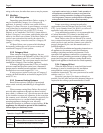
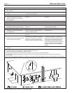
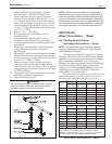
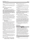
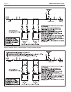
2.3.4 Vertical Combustion Air Terminal
When combustion air is taken from the roof, a
field-supplied rain cap or an elbow arrangement must be
used to prevent entry of rain water (see Figure 3). The
opening on the end of the terminal must be at least 12"
(30cm) above the point at which it penetrates the roof,
and high enough above the roof line to prevent blockage
from snow. When the vent terminates on the roof, the
combustion air must terminate at least 12" (30cm) below
the vent terminal.
2.4 Common Vent Test — Boilers
When an existing boiler is removed from a common
venting system, the common venting system is likely to
be too large for proper venting of the appliances
remaining connected to it.
At the time of removal of an existing boiler, the
following steps shall be followed with each appliance
remaining connected to the common venting system placed
in operation, while the other appliances remaining con-
nected to the common venting system are not in operation.
1. Seal any unused openings in the common venting
system.
2. Visually inspect the venting system for proper size
and horizontal pitch and determine there is no
blockage or restriction, leakage, corrosion and other
deficiencies which could cause an unsafe condition.
3. Insofar as it is practical, close all building doors
and windows and all doors between the space in
which the appliances remaining connected to the
common venting system are located and other
spaces of the building. Turn on clothes dryers and
any appliance not connected to the common venting
system. Turn on any exhaust fans, such as range
hoods and bathroom exhausts, so they will operate
at maximum speed. Do not operate a summer
exhaust fan. Close fireplace dampers.
4. Place in operation the appliance being inspected.
Follow the lighting instructions. Adjust thermostat
so appliance will operate continuously.