


Page 26
BRADFORD WHITE CORP.
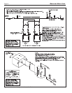
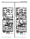
5.3 External Staging Control Wiring
WARNING
Improper field wiring may result in fire or explosion
which can cause property damage, severe injury, or
death. Make only wiring connections which are in
accordance with the Installation and Operation manual.
AVERTISSEMENT
Un câblage incorrect lors de l’installation peut causer
un incendie ou une explosion pouvant entraîner des
dommages matériels, de graves blessures ou la mort.
Ne faire seulement que les connexions conformes au
Manuel d’installation et d’exploitation.
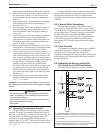
If controlling the stages of the BMT2 from an
external source (multiple boiler control, BAS, etc.), wire
Stage 1 to the terminals marked "Input Stage 1" and
"Stage 1", and wire Stage 2 to the terminals marked
"Input Stage 2" and "Stage 2". The "Local/Remote"
selector switch above the terminal strip must be placed
in the "Remote" position for the external controller to
manage the staging.
If it is intended to use the BMT2's on-board 2-
stage controller, no extra wiring is necessary. Ensure the
Local/Remote selector switch is in the "Local" position.
SECTION 6.
Operating Instructions
6.1 Sequence of Operation
Upon initiation of the main power switch, 120V
will be sent to multiple items. Among these are the open
contact fan relays, open contact ignitor relay, open
contact pump relay, ignition control module(s) and open
contact lock out indicators (the optional alarm package
uses this). In addition to these, 24V will travel through
the optional gas pressure switches and optional auto
reset high limit. 24V will then travel through the block
flue switch and the manual reset high limit to the
temperature controller.
Upon a call for heat from the BMT2’s internal
control or an external staging control, 24V travels
through the field interlock (if closed) and then to the
ignition control(s) “T-stat” terminal (500-750 models are
equipped with one ignition control and models 1000-
2000 are equipped with two ignition controls).
When “T-stat” on an ignition control is energized,
its fan will energize and the ignition control will seek
signal from the “pressure circuit”. The pressure circuits
consist of the flow switch and proof of fan.
Sizes 500-1000 calls for fan, fan prove, initiate
pump then prove flow, after which “pressure circuit” has
been satisfied.
Sizes 1250-2000 calls for pump, proof of flow,
initiate fan then prove fan, after which “pressure circuit”
has been satisfied. The fan prove will only occur for the
active stage that has been called.
When pressure circuit has been satisfied, proving
combustion air and adequate water flow, the hot surface
igniter will initiate. The ignition control checks that the
igniter current reached a predetermined level then will
dwell momentarily. When dwell time is complete the gas
valve will open.
After a 4-second trial for ignition, the igniter
switches off. Unless a flame is detected by the flame
sensor (a minimum value of 0.4µA), the gas valve will
close and The ignition module will either attempt
ignition again (up to three times) or will lock out if the
optional lockout ignition module is used.
If flame is sensed, the burner will continue to fire
as long as there is a call for heat and adequate flame
signal. If there is a subsequent loss of flame signal, the
burner will attempt re-ignition up to three times (only
once if optional lockout ignition is used.) When the call
for heat is satisfied, the gas valves(s) close and the
blowers continues to run for 30 seconds.
The pump will continue to run for 0.1 to 10
minutes, depending on what the pump time delay has
been set to. Brute Deluxe sizes 1,000-2,000 have two
ignition controls that control the individual stages. If one
ignition control should fail for any reason, the remaining
module can operate its burners independently. (Note that
if a single blower is disabled on units 1250-2000, the
other fan will continue to operate and safely allow the
boiler to run with a single stage.)
6.2 Filling the System
1. Ensure the system is fully connected. Close all
bleeding devices and open make-up water valve.
Allow system to fill slowly.
2. If make-up water pump is employed, adjust
pressure switch on pumping system to provide a
minimum of 12 psi (81.8 kPa) at the highest point
in the heating loop.
3. If a water pressure regulator is provided on the
make-up water line, adjust the pressure regulator to
provide at least 12 psi (81.8 kPa) at the highest
point in the heating loop.
4. Open bleeding devices on all radiation units at the
high points in the piping throughout the system,
unless automatic air bleeders are provided at such
points.
5. Run system circulating pump for a minimum of 30
minutes with the boiler shut off.
6. Open all strainers in the circulating system, check
flow switch operation, and check for debris. If debris
is present, clean out to ensure proper circulation.
7. Recheck all air bleeders as described in Step 4.
8. Check liquid level in expansion tank. With the
system full of water and under normal operating
pressure, the level of water in the expansion tank
should not exceed ¼ of the total, with the balance
filled with air.
9. Start up system according to the procedure in this
manual. Operate the entire system, including the