


Page 13
Brute Deluxe (500-2000)
Deluxe appliances are equipped to operate at
elevations up to 10,000 feet (3050m). Brute
Deluxe appliances may be adjusted to operate
properly at altitudes above 2500 feet (see Section
6.6.2) and the input will be reduced if the heating
value of the gas supply is below sea level values.
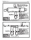
2. The maximum inlet gas pressure must not exceed
13" W.C (3.2kPa). The minimum inlet gas pressure
is 5" W.C. (1.2kPa).
3. Refer to Table 7, size supply.
4. Run gas supply line in accordance with all
applicable codes.
5. Locate and install manual shutoff valves in
accordance with state and local requirements.
6. A sediment trap must be provided upstream of the
gas controls.
7. All threaded joints should be coated with piping
compound resistant to action of liquefied
petroleum gas.
8. The appliance and its individual shutoff valve must
be disconnected from the gas supply piping during
any pressure testing of that system at test pressures
in excess of 1/2 PSIG (3.45kpa).
9. The unit must be isolated from the gas supply
system by closing its individual manual shutoff
valve during any pressure testing of the gas supply
piping system at test pressures equal to or less than
1/2 PSIG (3.45kpa).
10. The appliance and its gas connection must be leak
tested before placing it in operation.
11. Purge all air from gas lines.
WARNING
Do not use open flame to check for leaks. An open
flame could lead to explosion, which could result in
property damage, serious injury or death.
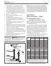
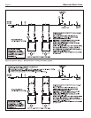
NOTE: The Brute Deluxe appliance and all other gas
appliances sharing the gas supply line must be firing at
maximum capacity to properly measure the inlet supply
pressure. The pressure can be measured at the supply
pressure port on the gas valve. Low gas pressure could
be an indication of an undersized gas meter, undersized
gas supply lines and/or an obstructed gas supply line.
SECTION 4A.
Water Connections —
Boiler
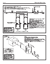
4A.1 Heating System Piping:
Hot Supply Connections — Boiler
NOTE: This appliance must be installed in a closed
pressure system with a minimum of 12 psi (82.7kPa)
static pressure at the boiler.
Hot water piping should be supported by suitable
hangers or floor stands. Do not support piping with this
appliance. Due to expansion and contraction of copper
pipe, consideration should be given to the type of
hangers used. Rigid hangers may transmit noise through
the system resulting from the piping sliding in the
hangers. It is recommended that padding be used when
rigid hangers are installed. Maintain 1" clearance to
combustibles for hot water pipes.
Pipe the discharge of the relief valve (full size) to a
drain or in a manner to prevent injury in the event of
pressure relief. Install an air purger, an air vent, a
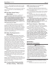
20°F 25°F 30°F 35°F
SIZE flow H/L flow H/L flow H/L flow H/L
gpm feet gpm feet gpm feet gpm feet
500 43 1.7 34 1.1 28 0.9 24 0.7
750 64 3.3 51 2.3 43 1.7 36 1.2
1000 85 5.0 68 3.6 57 3.1 49 2.2
1250 106 8.1 85 6.1 71 4.7 61 3.4
1500 128 10.0 102 7.2 85 5.5 73 4.2
1750 N/R N/R 119 10.5 99 8.4 85 5.8
2000 N/R N/R 136 12.5 113 10.4 97 8.3
Metric Equivalent
11°C 14°C 17°C 19°C
SIZE flow H/L flow H/L flow H/L flow H/L
lpm m lpm m lpm m lpm m
500 161 0.5 129 0.3 107 0.3 92 0.2
750 241 1.0 193 0.7 161 0.5 138 0.4
1000 321 1.5 257 1.1 214 0.9 184 0.7
1250 401 2.5 322 1.9 269 1.4 231 1.0
1500 483 3.0 386 2.2 322 1.7 276 1.3
1750 N/R N/R 451 3.2 375 2.6 322 1.8
2000 N/R N/R 515 3.8 429 3.2 368 2.5
Notes: gpm = gallons per minute, lpm = liters per minute,
H/L = headloss, ft = headloss in feet, m = headloss in meters.
Maximum temperature rise is 35°F (19°C), as shown. Headloss is
for boiler’s heat exchanger only. N/R = not recommended.
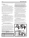
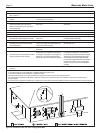
Table 8. Water Flow Requirements — BMT2H.Figure 5. Typical Gas Train Configuration.