


Page 4
BRADFORD WHITE CORP.
9 Fuel
N = Natural Gas
P = Propane
10 Altitude
A = 0–10,000 feet
11 Location
C = Indoor and Outdoor
12 Firing Mode
K = Two-stage
13 Revision
1 = First version of design
14 Heat Exchanger
B = Glass-lined cast iron / copper / bronze trim
(std. on BMT2V)
C = Glass-lined cast iron / copper
(std. on BMT2H)
K = Bronze / copper
N = Glass-lined cast iron / cupro-nickel
(n/a on water heaters)
P = Glass-lined cast iron / cu-nickel / bronze trim
S = Bronze / cupro-nickel
15 Option Code
X = Standard unit
J = CSD-1, FM, IRI, IL
16 Pump Options
H = Pump mounted BMT2V, hard water pump
N = Pump mounted (any), normal water pump
1.3 Warranty
Bradford White’s appliances are covered by a
limited warranty. Owners should submit online warranty
registration at
www.branfordwhite.com.
All warranty claims must be made to an authorized
Bradford White representative or directly to Customer
Service. Claims must include the serial number and
model (this information can be found on the rating plate),
installation date, and name of the installer. Shipping
costs are not included in the warranty coverage.
Some accessory items are shipped in separate
packages. Verify receipt of all packages listed on the
packing slip. Inspect everything for damage immediately
upon delivery, and advise the carrier of any shortages or
damage. Any such claims should be filed with the
carrier. The carrier, not the shipper, is responsible for
shortages and damage to the shipment whether visible or
concealed.
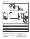
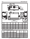
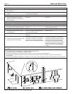
1.4 Dimensions
See Figures 1 and 2.
1.5 Locating the Appliance
The appliance should be located to provide
clearances on all sides for maintenance and inspection. It
should not be located in an area where leakage of any
connections will result in damage to the area adjacent to
the appliance or to lower floors of the structure.
When such a location is not available, it is
recommended that a suitable drain pan, adequately
drained, be installed under the appliance.
The appliance is design certified by CSA-
International for installation on combustible flooring; in
basements; in closets, utility rooms or alcoves. Brute
Deluxe Boilers or Water Heaters must never be
installed on carpeting. The location for the appliance
should be chosen with regard to the vent pipe lengths
and external plumbing. The unit shall be installed such
that the gas ignition system components are protected
from water (dripping, spraying, rain, etc.) during
operation and service (circulator replacement, control
replacement, etc.). When vented vertically, the Brute
Deluxe must be located as close as practical to a
chimney or outside wall. If the vent terminal and/or
combustion air terminal terminate through a wall, and
there is potential for snow accumulation in the local
area, both terminals should be installed at an appropriate
level above grade.
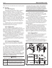
The dimensions and requirements that are shown in
Table 1 should be met when choosing the locations for
the appliance.
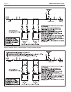
1.6 Locating Pump-Mounted Water Heater
with Respect to Storage Tank(s)
For best results, a pump-mounted Brute Deluxe
water heater should be located within 15 feet (4.6m) of
the storage tank(s). The pump is sized for 30 feet (9.1m)
of piping.
If the appliance must be installed with longer piping
runs, then larger diameter pipe or tubing shall be used.
Consult the factory for assistance.
1.7 Locating Pump-Mounted Boiler with
Respect to Return/Supply Header
For the best results, a pump-mounted Brute Deluxe
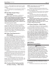
REQUIRED RECOMMENDED
APPLIANCE CLEARANCE FROM SERVICE ACCESS
SURFACE COMBUSTIBLE MATERIAL CLEARANCE
inches cm inches cm
Left Side 1 2.5 24 61
Right Side 1 2.5 24 61
Top 1 2.5 12 30
Back 1 2.5 **12** 30**
Front 1 2.5 36 91
Vertical
(Category 1) 6* 15.2*
Vent
Horizontal per UL1738 venting
(Category 3) system supplier’s
Vent instructions
*1" (2.5cm) when b-vent is used.
**When vent and/or combustion air connects to the back, recommended
clearance is 36" (91cm).
Table 1. Clearances.