


EN
|
20
Bosch Security Systems | 18 August 2005
LTC 8016/90 | Instruction Manual | Operation
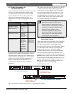
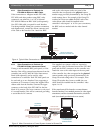
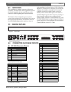
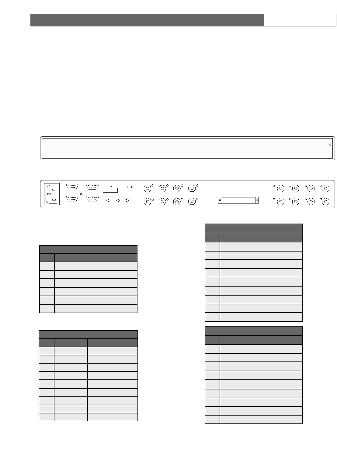
7.0 DEVICE OUTLINE
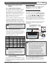
8.0 CONNECTOR AND CABLE PINOUTS
8.1 LTC 8016 Connector Pinouts
1
Pins are not numbered; the numbers represent
the pin sequence from left to right.
2
Pinouts used on units manufactured before
July, 2004 (date code 0426).
PC
INPUTS
15
16
13
14
11
12
9
10
8
6
5
3
4
2
LOOPING VIDEO 1-16
. . . . . . . . . . . . . . . . .
. . . . . . . . . . . . . . . . .
7
1
RS-232
RS-485 IN
RS-485 OUT
DATA
ETHERNET
10/100 BaseT
ACTLINK
CODE
BIPHASE IN
GROUP ID
0
2
6
4
8
0
2
6
4
8
0
2
6
4
8
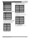
Figure 18 Rear Panel
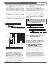
6-Position CODE Connector
1
Pin Connection
1 Shield
2 Biphase Data --
3 Biphase Data +
4 Shield
5 Biphase Data --
6 Biphase Data +
9-Pin PC Connector
Pin Connection Old Pinouts
2
1 –– ––
2 Rx Tx
3 Tx Rx
4 –– ––
5 Data Gnd Data Gnd
6 –– ––
7 RTS CTS
8 CTS RTS
9 –– ––
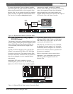
9-Pin RS-232 Connector
Pin Connection
1 Data Gnd
2 RTS
3 CTS
4 Tx
5 Rx
6 ––
7 Data Gnd
8 ––
9 ––
9-Pin RS-485 IN Connectors
Pin Connection
1 ––
2 TXD+
3 TXD--
4 RXD+
5 RXD--
6 ––
7 ––
8 ––
9 ––
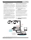
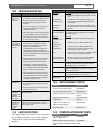
6.0 OPERATION
Once installation is finished, operation of this unit is
completely automatic. Refer to the applicable section of
the manual supplied with the control device and/or
camera for details regarding their features/functions.
The Interface Unit is designed to process camera
contact alarm and motion event messages from cameras
that support this functionality. The Interface Unit can
also detect Dark Alarm signal conditions when the
video amplitude level drops below 15 IRE. When the
Interface is connected to an Allegiant system using the
Allegiant data interface, messages can be sent to the
controller to notify the system of these events. By
default, camera contact alarm input 1 will result in a
standard Allegiant system alarm response, assuming an
alarm response mode has been configured in the
system. System responses to camera alarms 2 to 4, and
the Dark Alarm require programming of the Allegiant
system using the PC-based Allegiant LTC 8059 Master
Control Software, version 2.7 or later.
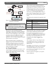
Allegiant Bilinx Data Interface
BOSCH
Status/Power
Figure 17 Front Panel