


EN
|
15
Bosch Security Systems | 18 August 2005
LTC 8016/90 | Instruction Manual | Installation
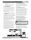
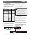
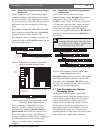
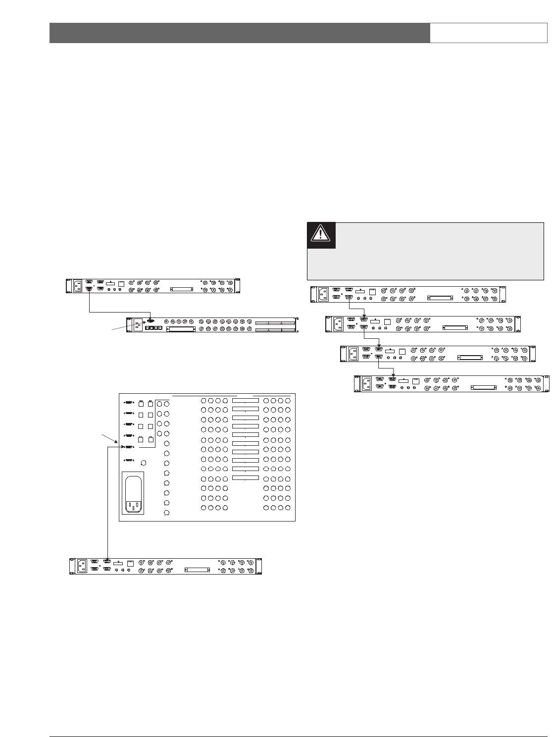
4.6.2 Allegiant Data Connections Using a Single
Interface Unit
Use the supplied 3 m (10 ft) data interface cable to
connect the Allegiant to the Interface Unit. Connect
one end of the cable to the Allegiant port selected in
the previous section, and the other end of the cable to
the Interface Unit port, according to the following
guide:
If an Allegiant CONSOLE, PRINTER, or ALARM
port is being used, connect the cable to the RS-232
connector on the rear of the Interface Unit.
If an Allegiant COM1 or COM2 port is being used,
connect the cable to the RS-485 IN connector on the
rear of the Interface Unit.
Once a connection is established between the
Interface Unit and the Allegiant, an automatic
download of the Allegiant’s physical camera-to-
logical camera table is sent to the Interface Unit.
Prior to this update, the front panel LED on the
Interface Unit flashes to indicate that it is waiting for
the information to be received. Once the LED
changes to a steady condition, configuration is
complete.
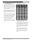
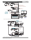
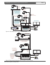
4.6.3 Allegiant Data Connections Using Multiple
Interface Units
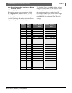
Up to 31 units can be connected to a single
Allegiant switcher, using a daisychain data interface
configuration. This provides support for up to
496 Bilinx cameras. Since the same data is being sent
to all Interface Units in the chain, it does not matter
what order is used when connecting the data lines
between the units. Simply connect the supplied
3 m (10 ft) data interface cable from the RS-485 OUT
connector of one Interface Unit to the RS-485 IN of
the next unit.
To properly terminate the RS-485 data
connection, the last Interface Unit in the series
(i.e., furthest from the Allegiant switcher) must
have its left-most Group ID set to 9.
Daisychain configurations can only be used when the
data connection from the controller to the Interface
Unit utilizes either an RS-232 or RS-485 data port.
Do not use this method if the data connection from a
controller uses the biphase data port.
4.7 Data Connection to a Biphase
Generating Device
The Interface Unit is designed to support data
connections from other head-end controller devices
with the ability to generate Bosch Security Systems
biphase control data. Since biphase protocol is a
single direction communication format, control of
P/T/Z functions, auxiliaries, and pre-positions are
fully supported, but it is not possible to receive any
data back from the camera site. This means that
reporting of alarms or other camera site-related events
is not possible with a biphase data connection.
LTC 8016 Interface Unit
2 m (6 ft) Supplied
Data Interface Cable
LTC8200
KEYBOARD
CONSOLE
MONITOR OUTPUTS
CAMERA INPUTS
ALARM 1-8
BIPHASE OUT
BIPHASE OUT
RELAY OUT
1
9
2
10
3
11
4
12
5
13
14
6
7
15
8
16
5
4
1
2
3
. . . . . . . . . . . . . . . . .
. . . . . . . . . . . . . . . . .
ALARM 9-16
BIPHASE OUT
PC
INPUTS
15
16
13
14
11
12
9
10
8
6
5
3
4
2
LOOPING VIDEO 1-16
. . . . . . . . . . . . . . . . .
. . . . . . . . . . . . . . . . .
7
1
RS-232
RS-485 IN
RS-485 OUT
DATA
ETHERNET
10/100 BaseT
ACTLINK
CODE
BIPHASE IN
GROUP ID
0
2
6
4
8
0
2
6
4
8
0
2
6
4
8
LTC 8200 Allegiant Series Switcher
Allegiant
CONSOLE Port
LTC 8016 Interface Unit
2m (6ft) Supplied
Data Interface Cable
PC
INPUTS
15
16
13
14
11
12
9
10
8
6
5
3
4
2
LOOPING VIDEO 1-16
. . . . . . . . . . . . . . . . .
. . . . . . . . . . . . . . . . .
7
1
RS-232
RS-485 IN
RS-485 OUT
DATA
ETHERNET
10/100 BaseT
ACTLINK
CODE
BIPHASE IN
GROUP ID
0
2
6
4
8
0
2
6
4
8
0
2
6
4
8
LTC 8600 Allegiant Series Switcher
Allegiant
COM Port 1
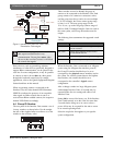
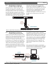
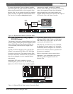
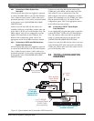
Figure 8 Data Interface Connection Detail When
Using Large Model Allegiant System
Figure 7 Data Interface Connection Detail When
Using Large Model Allegiant System
2m (6ft) Supplied
Data Interface Cable
PC
INPUTS
15
16
13
14
11
12
9
10
8
6
5
3
4
2
LOOPING VIDEO 1-16
. . . . . . . . . . . . . . . . .
. . . . . . . . . . . . . . . . .
7
1
RS-232
RS-485 IN
RS-485 OUT
DATA
ETHERNET
10/100 BaseT
ACTLINK
CODE
BIPHASE IN
GROUP ID
0
2
6
4
8
0
2
6
4
8
0
2
6
4
8
PC
INPUTS
15
16
13
14
11
12
9
10
8
6
5
3
4
2
LOOPING VIDEO 1-16
. . . . . . . . . . . . . . . . .
. . . . . . . . . . . . . . . . .
7
1
RS-232
RS-485 IN
RS-485 OUT
DATA
ETHERNET
10/100 BaseT
ACTLINK
CODE
BIPHASE IN
GROUP ID
0
2
6
4
8
0
2
6
4
8
0
2
6
4
8
PC
INPUTS
15
16
13
14
11
12
9
10
8
6
5
3
4
2
LOOPING VIDEO 1-16
. . . . . . . . . . . . . . . . .
. . . . . . . . . . . . . . . . .
7
1
RS-232
RS-485 IN
RS-485 OUT
DATA
ETHERNET
10/100 BaseT
ACTLINK
CODE
BIPHASE IN
GROUP ID
0
2
6
4
8
0
2
6
4
8
0
2
6
4
8
PC
INPUTS
15
16
13
14
11
12
9
10
8
6
5
3
4
2
LOOPING VIDEO 1-16
. . . . . . . . . . . . . . . . .
. . . . . . . . . . . . . . . . .
7
1
RS-232
RS-485 IN
RS-485 OUT
DATA
ETHERNET
10/100 BaseT
ACTLINK
CODE
BIPHASE IN
GROUP ID
0
2
6
4
8
0
2
6
4
8
0
2
6
4
8
2m (6ft) Supplied
Data Interface Cable
2m (6ft) Supplied
Data Interface Cable
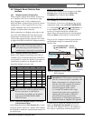
Up to 31 units total (when using large Allegiant System Controller)
Figure 9 Data Interface Connection Detail When
Using Multiple Interface Units